Adaptive energy transfer system and method

a technology of energy transfer system and energy transfer method, which is applied in the direction of non-rotary current collector, transportation and packaging, railway signalling, etc., can solve the problems of affecting the employment of devices and wayside equipment (as well as the location of such devices and equipment) in the transportation industry

Active Publication Date: 2014-02-13
GE GLOBAL SOURCING LLC
View PDF4 Cites 16 Cited by
  • Summary
  • Abstract
  • Description
  • Claims
  • Application Information

AI Technical Summary

Problems solved by technology

This can hinder the employment of devices and wayside equipment (as well as location of such devices and equipment) within the transportation industry.

Method used


Image

  • Adaptive energy transfer system and method
  • Adaptive energy transfer system and method
  • Adaptive energy transfer system and method

Examples


Embodiment Construction

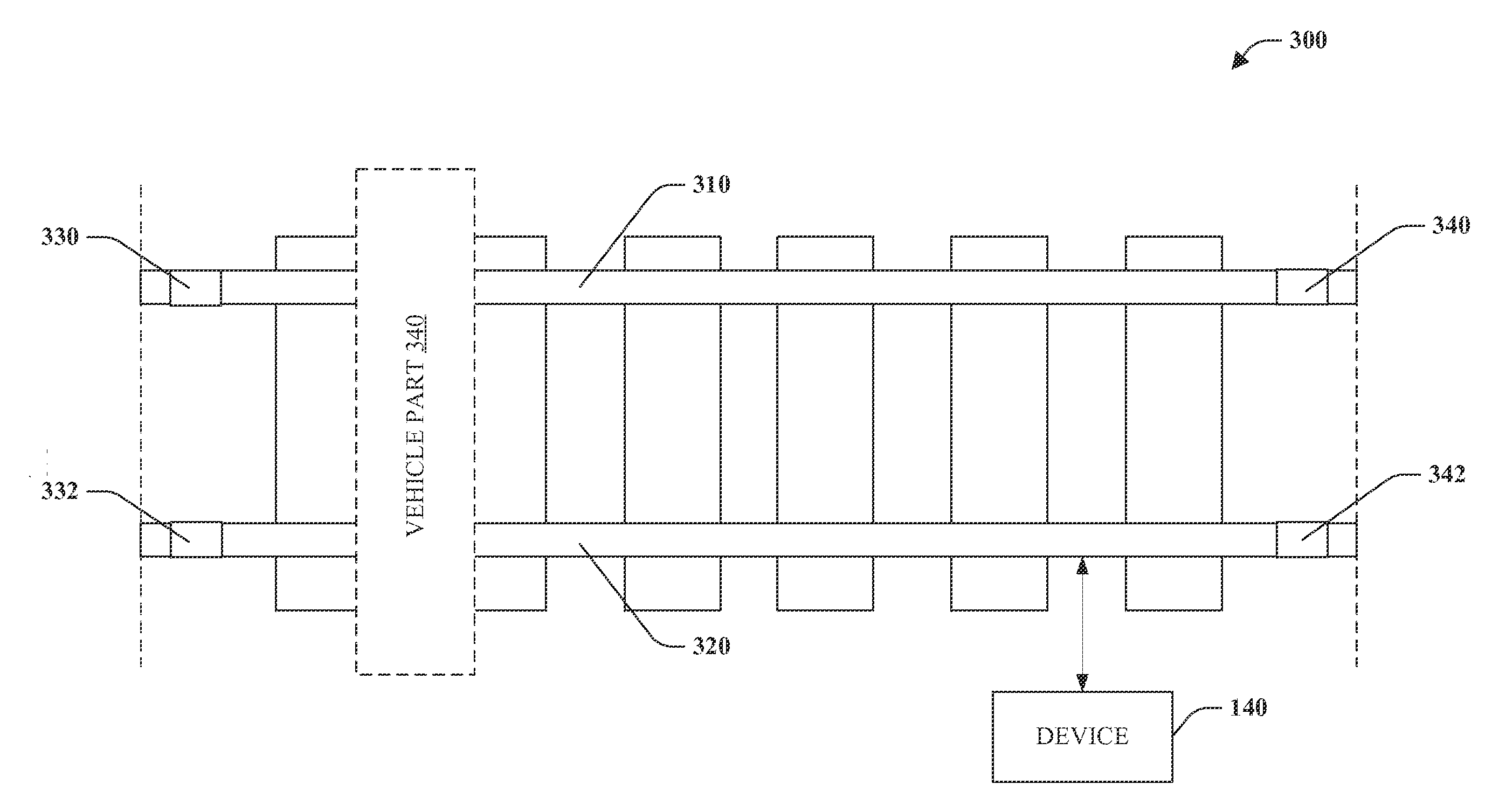
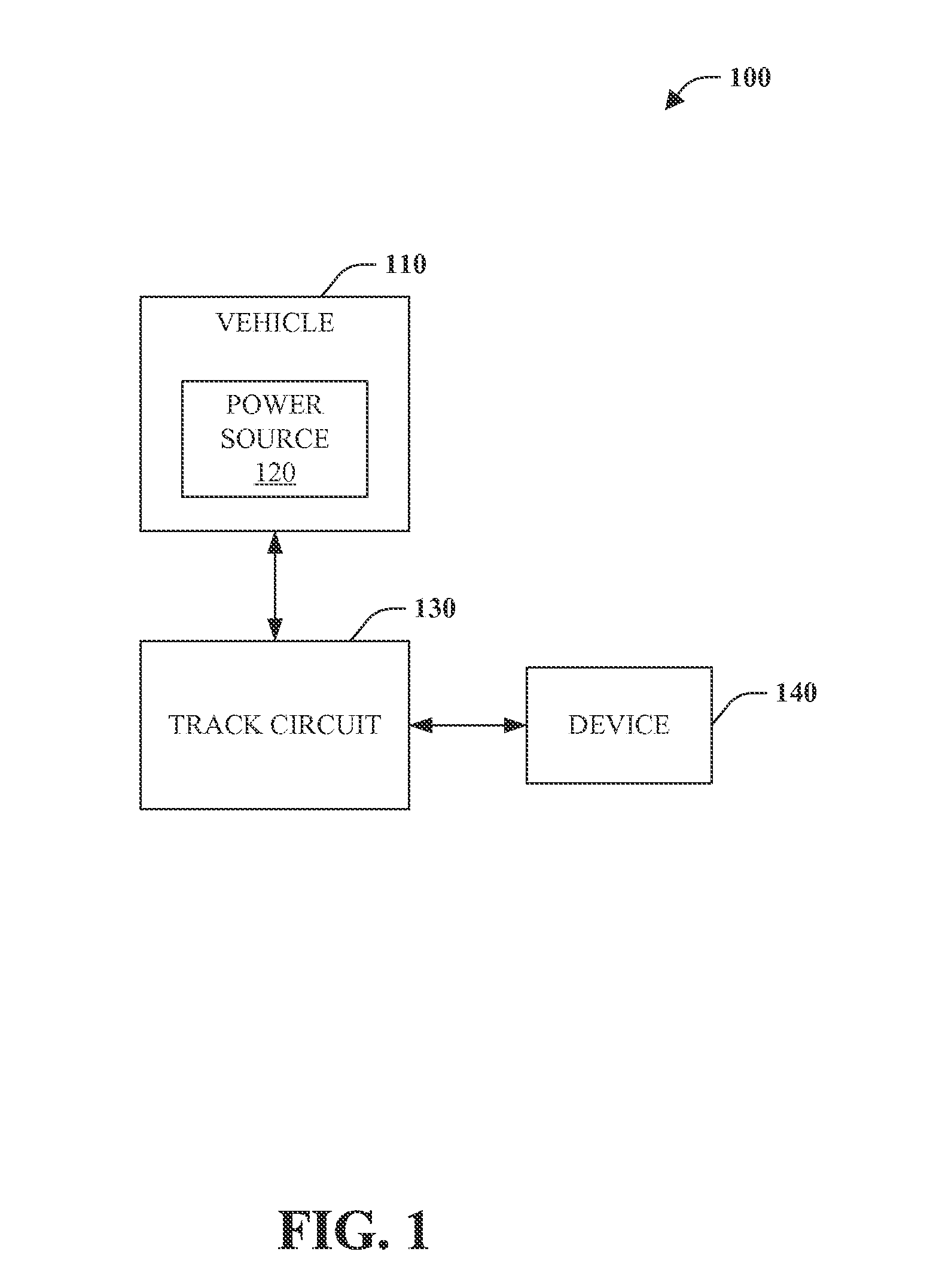
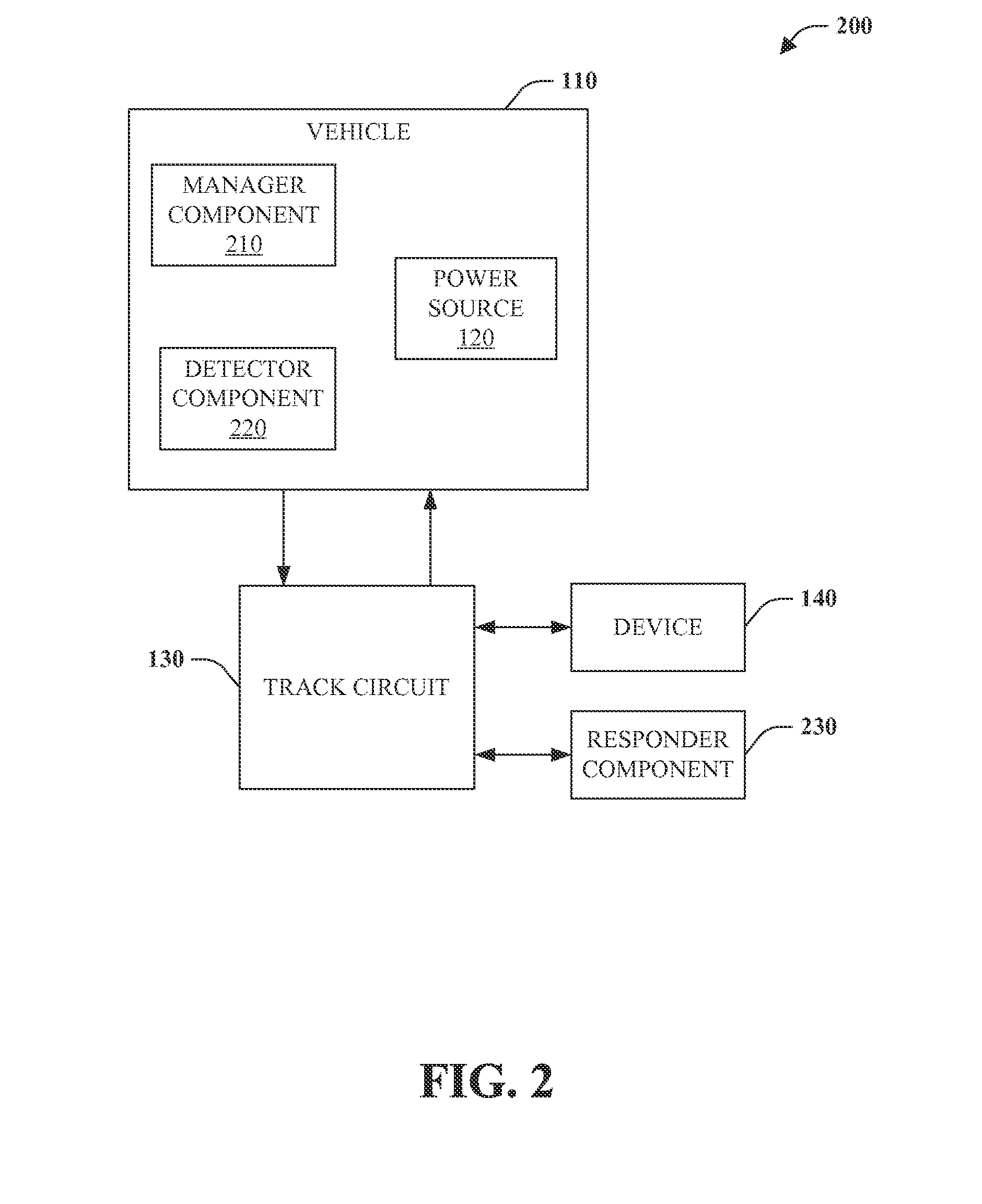
[0019]Embodiments of the invention relate to methods and systems for transferring energy from a vehicle to a device via a track circuit. In particular, a vehicle can include equipment for transferring energy from a power source of the vehicle to a track circuit and a device coupled to the track circuit. For example, the device may be off-board the vehicle, and the power / energy that is transferred may be used to power the device. The track circuit can include a section of track having a first insulated member between a first rail and a second rail and a second insulated member a distance from the first insulated member. Based on a power input for the device, the transfer of energy can be adjusted (e.g., increased amount, decreased amount, frequency change, and the like). A signal can be communicated to the vehicle based on receipt of the transferred energy.

[0020]The term “client asset” as used herein means a fixed asset or a mobile asset that is owned and / or operated by a client enti...


PUM


Abstract

Systems and methods of the invention relate to transferring energy from a vehicle to a device via a track circuit. Embodiments of the present invention include a power source of a vehicle that can be utilized to transfer energy through a track circuit to a device coupled thereto. The track circuit can include a section of track having a first pair of insulated joints located on a first rail and a second pair of insulated joints on a second rail, each pair separated by a distance. Moreover, a signal can be communicated to the vehicle based on receipt of the transferred energy.

Description

CROSS-REFERENCE TO RELATED APPLICATIONS[0001]This application claims the benefit of U.S. Provisional Application Ser. No. 61 / 681,843, filed Aug. 10, 2012, and entitled “ADAPTIVE ENERGY TRANSFER SYSTEM AND METHOD.” The entirety of the aforementioned application is incorporated herein by reference.BACKGROUND[0002]1. Technical Field[0003]Embodiments of the subject matter disclosed herein relate to transferring a portion of energy from a vehicle to a device.[0004]2. Discussion of Art[0005]Devices or equipment can be located at geographic areas that do not have a power source or may be located in an area that a power source is not accessible. This can hinder the employment of devices and wayside equipment (as well as location of such devices and equipment) within the transportation industry.[0006]It may be desirable to have a system and method for power systems that differ from those that are currently available.BRIEF DESCRIPTION[0007]In one embodiment, a method is provided. The method i...

Claims


Application Information

Patent Timeline
Patent Type & Authority Applications(United States)
IPC IPC(8): H01R41/00
CPCH01R41/00B60M3/00B61L1/181B61L1/20B61L3/125B61L13/047B61L27/20
Inventor NOFFSINGER, JOSEPH FORRESTMITTI, AARON RICHARD
Owner GE GLOBAL SOURCING LLC
Why Eureka
Try Eureka