
Transfer control method of continuous paper and printer

a control method and printer technology, applied in the field of printing machines, can solve the problems of transfer error and inability to eliminate transfer errors, and achieve the effects of reducing the transfer error in the remaining transfer section, preventing accumulation thereof, and high precision

Inactive Publication Date: 2014-02-13
SEIKO EPSON CORP
View PDF3 Cites 8 Cited by
  • Summary
  • Abstract
  • Description
  • Claims
  • Application Information

AI Technical Summary

Benefits of technology

The present disclosure aims to provide a printer that can achieve high precise printing while also preventing accumulation in transfer errors. This is achieved through a balance between the transfer precision of the paper feed roller and other factors.

Problems solved by technology

If the continuous paper slips on the paper feed roller due to the increased transfer load of the continuous paper, the actual feeding amount is decreased relative to the actual feeding amount (set feeding amount) which can be calculated from the rotational amount of the paper feed roller, which creates a transfer error.
However, the transfer control method does not consider the transfer error in a transfer section, but consider the transfer error during printing.
For this reason, after the printing is completed, it is not possible to eliminate the transfer error which is created when the paper is fed to the next page.
Further, since it is not possible to prevent accumulation in the transfer errors, a printing start position shift may be increased at a next page in a case where the transfer amount is high due to the many number of pages.
There may be an error within a play range between the engagement hole and the engagement portion, but a transfer error is not accumulated even though the transfer amount is increased.

Method used


Image

  • Transfer control method of continuous paper and printer
  • Transfer control method of continuous paper and printer
  • Transfer control method of continuous paper and printer

Examples


Embodiment Construction

[0027]Now, an embodiment of a printer and a transfer control method of continuous paper according to an aspect of the disclosure will be described with reference to the accompanying drawings.

Overall Configuration

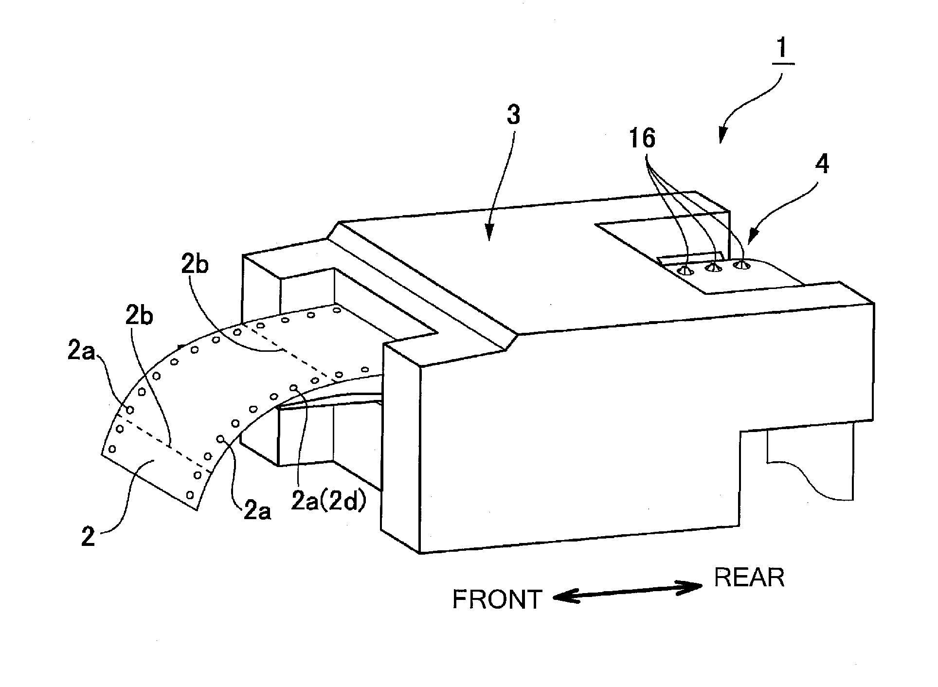
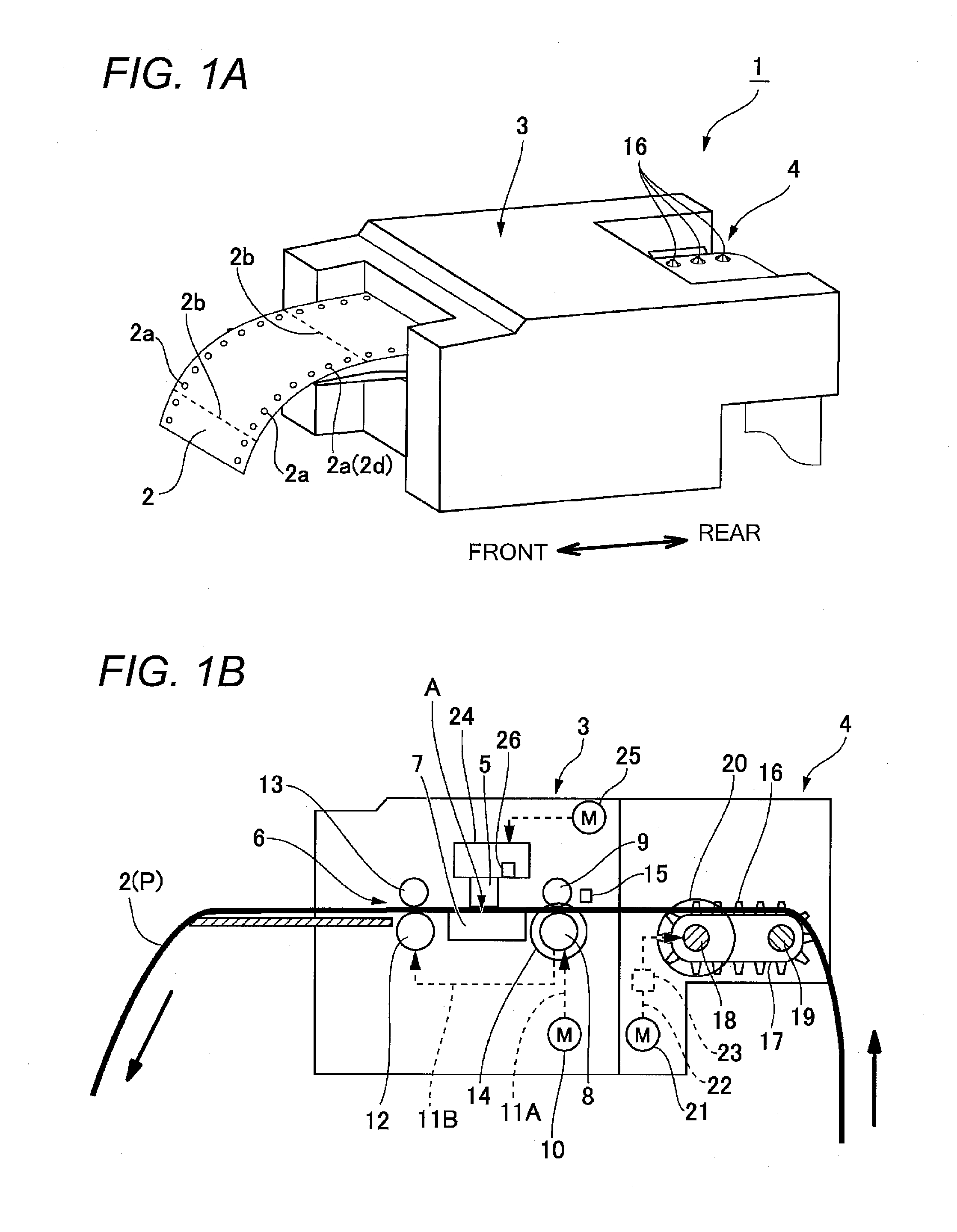
[0028]FIG. 1A is a perspective view of a printer, and FIG. 1B is a longitudinal cross-sectional view schematically illustrating major parts of the printer. A printer 1 is configured to print continuous paper 2 (recording medium) with sprocket holes (engagement holes) 2a formed at both end portions thereof along a paper width direction. The printer 1 includes a printer body 3 and a tractor 4 detachably mounted to a rear portion of the printer body 3 in a front-rear direction of the printer. The continuous paper 2 is conveyed from a rear side of the printer into the printer body 3 by the tractor 4, and then is discharged to a front side of the printer from the printer body 3 after printing is performed.

[0029]In the printer body 3, a transfer path P is set in a straight type in...


PUM


Abstract

A transfer control method of continuous paper includes controlling a transfer amount of the continuous paper based on a rotational amount detected by a roller feeding amount detecting unit which detects the rotational amount of a paper feed roller, when each page of the continuous paper is printed, and when the printing on each page is completed, performing a cueing process of transferring the continuous paper until a printing start position of a next page reaches the printing position. The cueing process includes transferring the continuous paper until the continuous paper reaches a reference transfer position based on the feeding amount of the tractor detected by a tractor feeding amount detecting unit for detecting a feeding amount of the tractor and after the continuous paper reaches the reference transfer position, setting the transfer amount of the continuous paper as a target feeding amount.

Description

[0001]The disclosure of Japanese Patent Application No. 2012-175755 filed on Aug. 8, 2012, including specification, drawings and claims is incorporated herein by reference in its entirety.BACKGROUND[0002]1. Technical Field[0003]An aspect of the present disclosure relates to a printer employing a paper feed roller and a tractor as a transfer mechanism for transferring continuous paper, and more particularly, to a transfer control method of continuous paper and a printer which transfers the continuous paper with high precision.[0004]2. Related Art[0005]Heretofore, in printers capable of printing continuous paper with sprocket holes (engagement holes) formed on both ends thereof, a tractor and a paper feed roller are used as a transfer mechanism for transferring the continuous paper. The tractor includes tractor pins (engagement portions) which can be inserted into the sprocket holes formed along a longitudinal direction of the continuous paper, a tractor belt with the tractor pins for...

Claims


Application Information

Patent Timeline
Patent Type & Authority Applications(United States)
IPC IPC(8): B41J13/00
CPCB41J13/0009B41J11/26B41J11/42B41J15/04
Inventor MAEDA, HIROYUKI
Owner SEIKO EPSON CORP
Learn More