Printing apparatus and printing method

a printing apparatus and printing method technology, applied in the direction of printing apparatus, non-metallic protective coating application, coating, etc., can solve the problems of significant challenge in preventing such flowing liquid, affecting the reliability of connection, etc., and achieve the effect of preventing the spread of liquid resists and high precision

Inactive Publication Date: 2010-09-21
NITTO DENKO CORP
View PDF11 Cites 2 Cited by
  • Summary
  • Abstract
  • Description
  • Claims
  • Application Information

AI Technical Summary

Benefits of technology

[0013]It is therefore an object of the present invention to provide a printing apparatus which can prevent a liquid resist from flowing to a portion where the formation of the resist is intrinsically unnecessary and can print a liquid resist with high precision and to a printing method using the printing apparatus.
[0015]In the printing apparatus, before the elongated base material on which the liquid resist is printed by the printing unit is wound up by the wind-up unit, the solvent in the liquid resist is sucked up by the suction unit. Since the solvent is thus sucked up from the printed liquid resist immediately after printing, the flowing thereof is immediately suppressed thereafter. In addition, because the solvent in the liquid resist is sucked up by the suction unit, the ambient atmosphere of the liquid resist is under a negative pressure and the spread of the liquid resist can be prevented more reliably. As a result, it is possible to prevent the liquid resist from flowing to a portion where the formation of the liquid resist is intrinsically unnecessary and to print the liquid resist with high precision.
[0017]When the suction unit is positioned within the range of 1000 mm downstream of the placement portion for the elongated base material in the printing unit in the transport direction of the elongated base material, the flowing of the liquid resist can be prevented more reliably.
[0021]When the suction unit is provided in the direction intersecting the transport direction of the elongated base material, suction can be performed in a direction orthogonal to the transport direction of the elongated base material, i.e., in a widthwise direction. As a result, it is possible to uniformly prevent the flowing of the liquid resist in the widthwise direction.
[0023]In the case where the suction unit comprises the portion exposed from the elongated base material in the direction orthogonal to the transport direction of the elongated base material, when the suction unit is projected in the direction of projection, reliable suction can be performed with respect to the elongated base material along the entire width thereof. As a result, the flowing of the liquid resist can be prevented more reliably.
[0025]In the printing method, before the elongated base material on which the liquid resist is printed in the printing step is wound up in the wind-up step, the solvent in the liquid resist is sucked up in the suction step. Since the solvent is thus sucked up from the printed liquid resist immediately after printing, the flowing thereof is immediately suppressed thereafter. In addition, because the solvent in the liquid resist is sucked up in the suction step, the ambient atmosphere of the liquid resist is under a negative pressure and the spread of the liquid resist can be prevented more reliably. As a result, it is possible to prevent the liquid resist from flowing to a portion where the formation of the liquid resist is intrinsically unnecessary and to print the liquid resist with high precision.

Problems solved by technology

However, there is a case where the liquid resist printed by screen printing flows between the conductive patterns to undesirably cover a portion which intrinsically need not be covered.
In such a case, the solder resist formed on the portion which need not be covered inhibits mounting of electronic components or at least degrades connection reliability, even though the mounting is not inhibited thereby.
With the recent miniaturization of the conductive patterns, it has been a significant challenge to prevent such flowing of the liquid resist.

Method used


Image

  • Printing apparatus and printing method
  • Printing apparatus and printing method
  • Printing apparatus and printing method

Examples


example 1

[0072]An elongated base material 2 (a width of 300 mm) in which a insulating base layer made of a polyimide resin having a thickness of 25 μm was laminated on a metal supporting board made of a stainless steel foil having a thickness of 25 μm, and conductive patterns having a wire width of 12 μm, a wire-to-wire spacing of 13 μm, and a thickness of 10 μm were printed on the insulating base layer was prepared and wound around a feed-out roll 7.

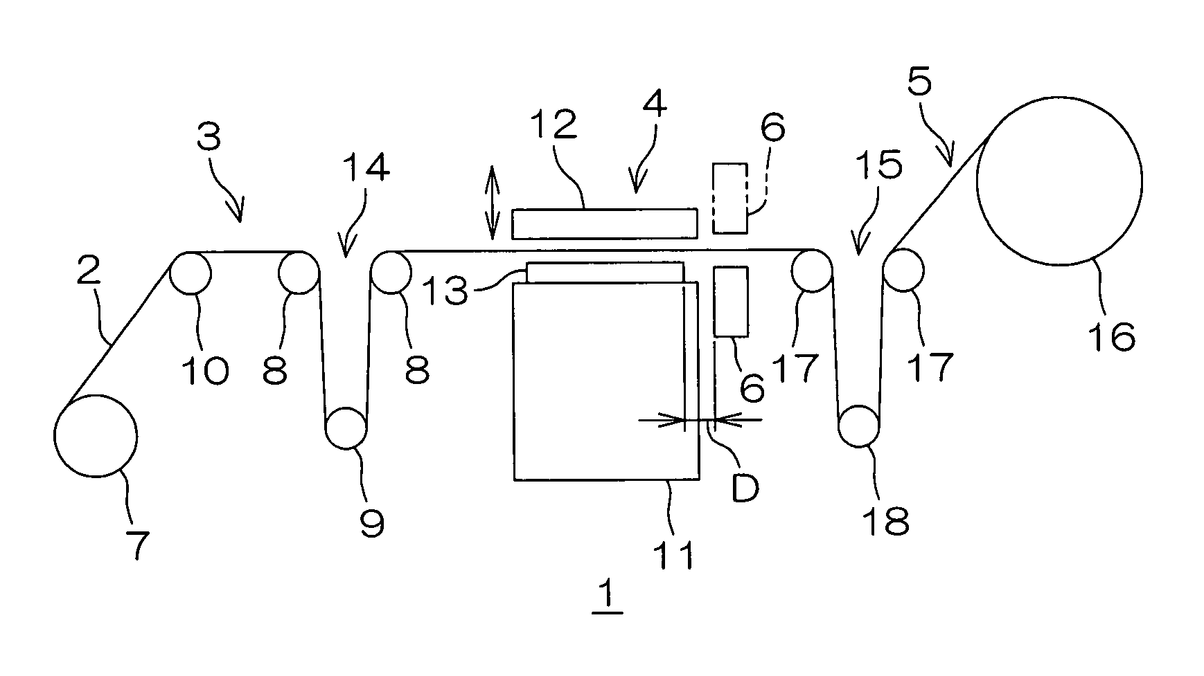
[0073]The feed-out roll 7 having the elongated base material 2 wound therearound is set in the printing apparatus 1 shown in FIG. 1 and a liquid resist (SN-9000 (solid content of 40 wt %) commercially available from Hitachi Chemical Co., Ltd.) was printed on the print area of the elongated base material 2 to have a thickness of 36 μm using the printing apparatus 1 shown in FIG. 1, thereby forming a solder resist covering the conductive patterns on the insulating base layer.

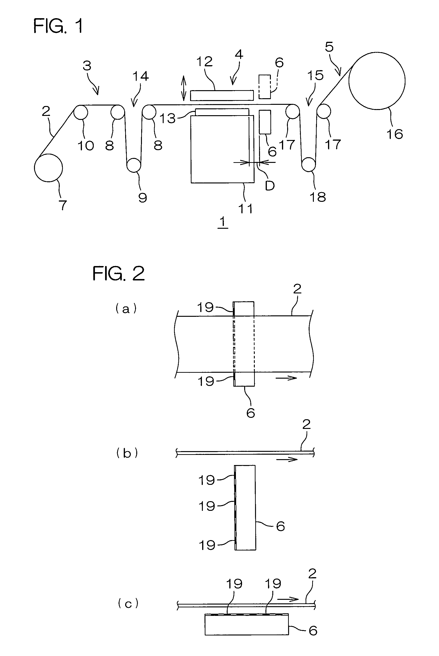
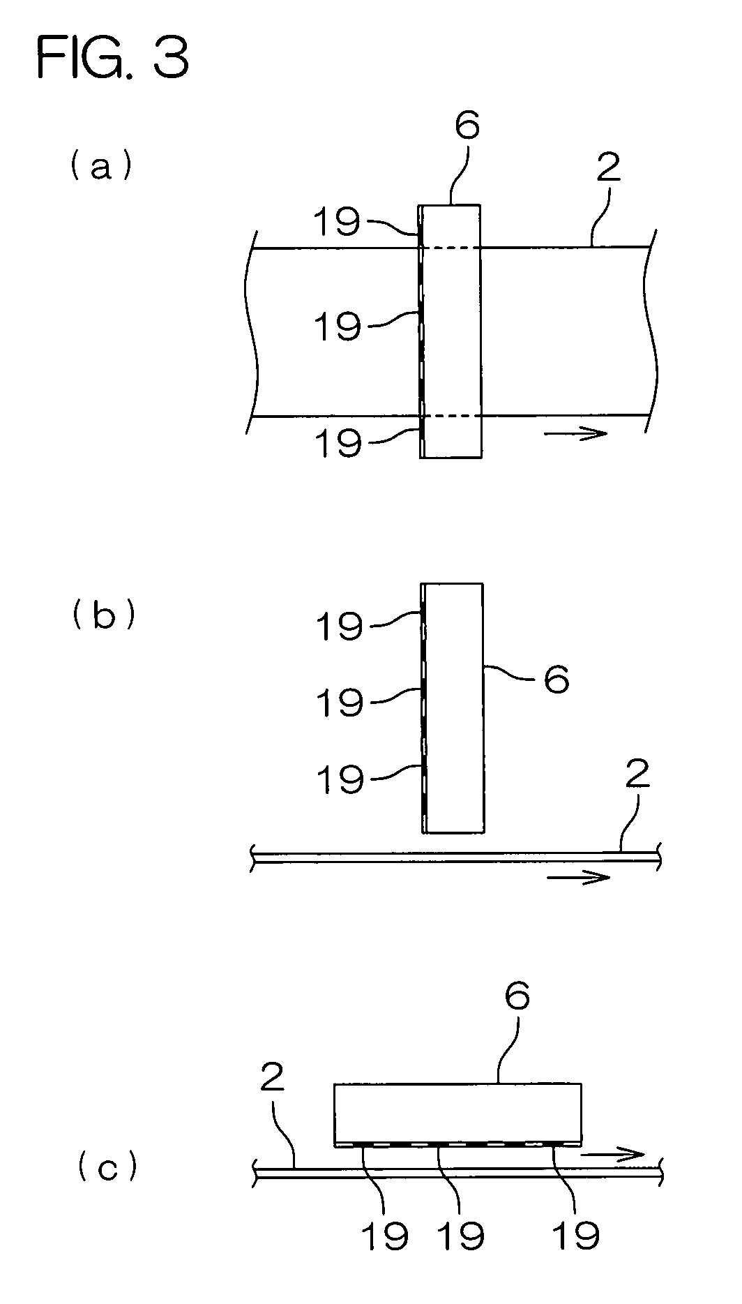
[0074]In the printing apparatus 1, the suction unit 6 was formed in the s...


PUM

PropertyMeasurementUnit
diameteraaaaaaaaaa
diameteraaaaaaaaaa
lengthaaaaaaaaaa

Abstract

A printing apparatus includes a feed-out unit for feeding out an elongated base material which is wound up in a roll, a printing unit for printing a liquid resist onto the elongated base material that is fed out of the feed-out unit, a wind-up unit for winding up the elongated base material on which the liquid resist is printed by the printing unit into a roll, and a suction unit positioned between the printing unit and the wind-up unit in a transport direction of the elongated base material for sucking up a solvent in the liquid resist.

Description

CROSS-REFERENCE TO RELATED APPLICATION[0001]The present application claims priority from Japanese Patent Application No. 2006-97971 filed on Mar. 31, 2006, the content of which is hereby incorporated by reference into this application.BACKGROUND OF THE INVENTION[0002]1. Field of the Invention[0003]The present invention relates to a printing apparatus and to a printing method and, more particularly, to a printing apparatus for continuously printing a liquid resist onto an elongated base material and to a printing method using the printing apparatus.[0004]2. Description of the Related Art[0005]It has been known to continuously print conductive patterns onto a belt-like elongated film by a TAB (Tape Automated Bonding) method.[0006]To form a solder resist covering the conductive patterns, the method includes forming the conductor patterns, continuously screen-printing a liquid resist, and then drying the printed liquid resist. In consideration of a filling property of the liquid resist ...

Claims


Application Information

Patent Timeline
Patent Type & Authority Patents(United States)
IPC IPC(8): B41M1/12
CPCH05K3/0091H05K1/0393H05K3/1216H05K2203/1545H05K2203/0759H05K2203/082H05K3/28G03F7/16
Inventor TSUNEKAWA, MAKOTOBABA, TOSHIKAZU
Owner NITTO DENKO CORP
Why Eureka
Try Eureka