

Device module and method of manufacturing the same
a technology of device modules and housings, applied in the direction of electrical apparatus construction details, instruments, coatings, etc., can solve the problems reducing the difficulty of inserting the second portion of transmission cables into the housing recess of the die, etc., and achieving the effect of reducing the possibility of movement of external connections
- Summary
- Abstract
- Description
- Claims
- Application Information
AI Technical Summary
Benefits of technology
Problems solved by technology
Method used
Image

Examples
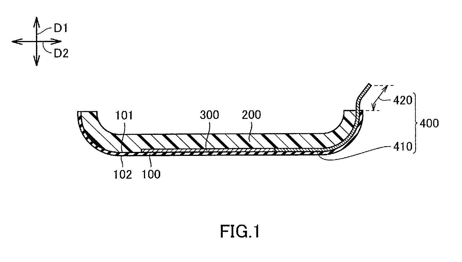
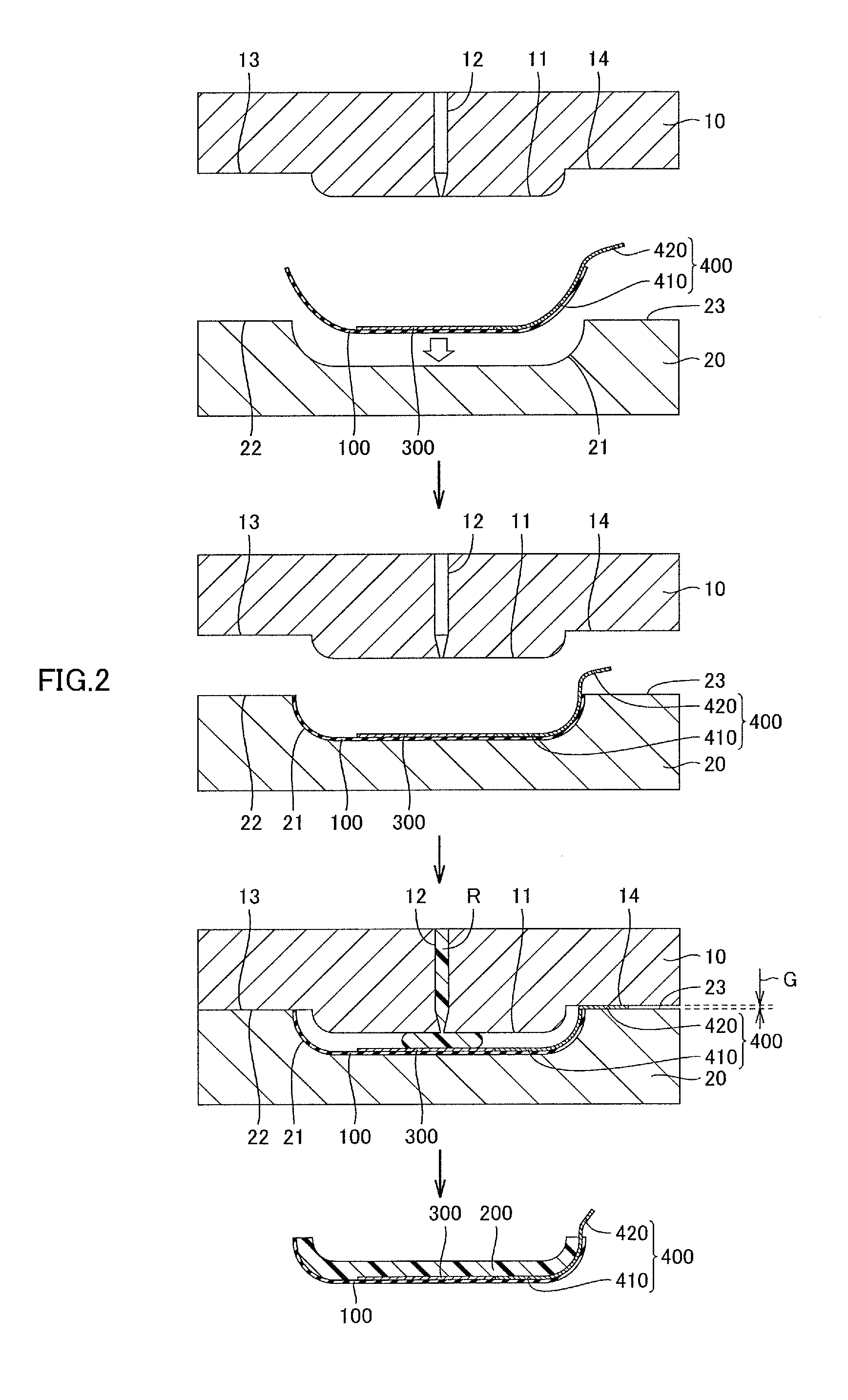
first embodiment
[0156]10: first die
[0157]20: second die
[0158]R: plastic material
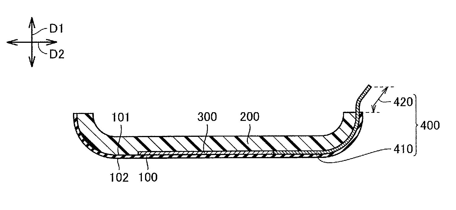
[0159]100: base[0160]101: first face[0161]102: second face
[0162]200: plastic part
[0163]300: touch sensor (device)
[0164]400: external connection[0165]410: embedded portion[0166]420: lead-out portion
second embodiment
[0167]10′: first die
[0168]20: second die
[0169]R: plastic material
[0170]100′: base[0171]101′: first face[0172]102′: second face[0173]110′: base body[0174]120′: affixed portion
[0175]200: plastic material
[0176]300: touch sensor (device)
[0177]400: external connection[0178]410: embedded portion[0179]420: lead-out portion
third embodiment
[0180]10: first die
[0181]20′: second die
[0182]R: plastic material
[0183]100″: base[0184]101″: first face[0185]102″: second face[0186]200′: plastic part[0187]210′: plastic body[0188]220′: protruding portion[0189]230′: protruding portion
[0190]300: touch sensor (device)
[0191]400′: external connection[0192]410′: embedded portion[0193]420′: lead-out portion[0194]421′: fixed portion[0195]422′: free portion
PUM
 Abstract
Description
Claims
Application Information