Motor controller, image processing apparatus including the motor controller, and motor control method

a technology of motor controller and image processing apparatus, which is applied in the direction of program control, electronic commutator, dynamo-electric converter control, etc., can solve the problem of unsuitable transportation

Active Publication Date: 2014-02-13
RICOH KK
View PDF11 Cites 11 Cited by
  • Summary
  • Abstract
  • Description
  • Claims
  • Application Information

AI Technical Summary

Benefits of technology

[0014]In view of the above, it is a general object of the present invention to provide an improved motor controller operatively connected to a motor having an output shaft. The motor controller includes a rotary detector, a drive controller, and a driver. The rotary detector detects a rotation direction and a rotation amount of the output shaft of the motor to generate an actual rotary signal. The drive controller receives a target rotary signal indicating a target rotary direction and a target rotary amount, and generates a control signal based on the actual rotary signal and the target rotary signal generated by the rotary detector. The driver supplies driving power to the motor based on the control signal from the drive controller. When the motor is in a hold state, the drive controller periodically generates a reverse control signal whose polarity is reversed for a predetermined reverse time period T2 per a predetermined one reverse cycle T1. When the reverse control signal is not output from the driver controller for a certain lock detection time period Tr that is longer than the revere cycle T1 of the control signal, the driver blocks supply of the driving power to the motor, to put the motor in a locked state.

Problems solved by technology

However, the driver that drives the motor based on a control signal generally deems the motor to be locked and idle when the control signal is not changed for a predetermined time period, and the driver too enters a locked state in which the driver blocks output to the brushless motor.
However, with this arrangement, this example cannot distinguish between the locked state determined when the control signal is not changed for a predetermined time period and the position hold state, which may erroneously recognize the hold state as the locked state.
When the hold state is erroneously recognized as the locked state, the driver stops the output to the motor, such that the sheet and document cannot be hold at an intended position, and the suitable transportation cannot be performed.

Method used


Image

  • Motor controller, image processing apparatus including the motor controller, and motor control method
  • Motor controller, image processing apparatus including the motor controller, and motor control method
  • Motor controller, image processing apparatus including the motor controller, and motor control method

Examples


Embodiment Construction

[0029]In describing preferred embodiments illustrated in the drawings, specific terminology is employed for the sake of clarity. However, the disclosure of this patent specification is not intended to be limited to the specific terminology so selected, and it is to be understood that each specific element includes all technical equivalents that operate in a similar manner and achieve a similar result.

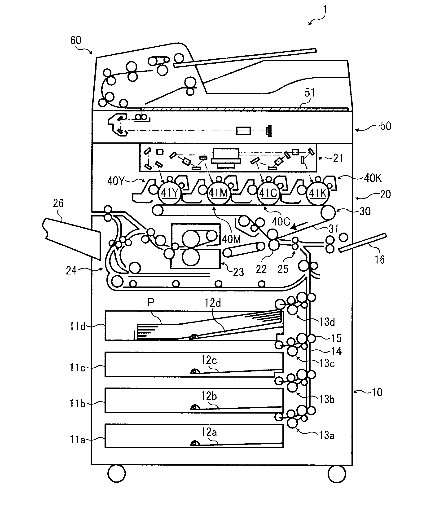
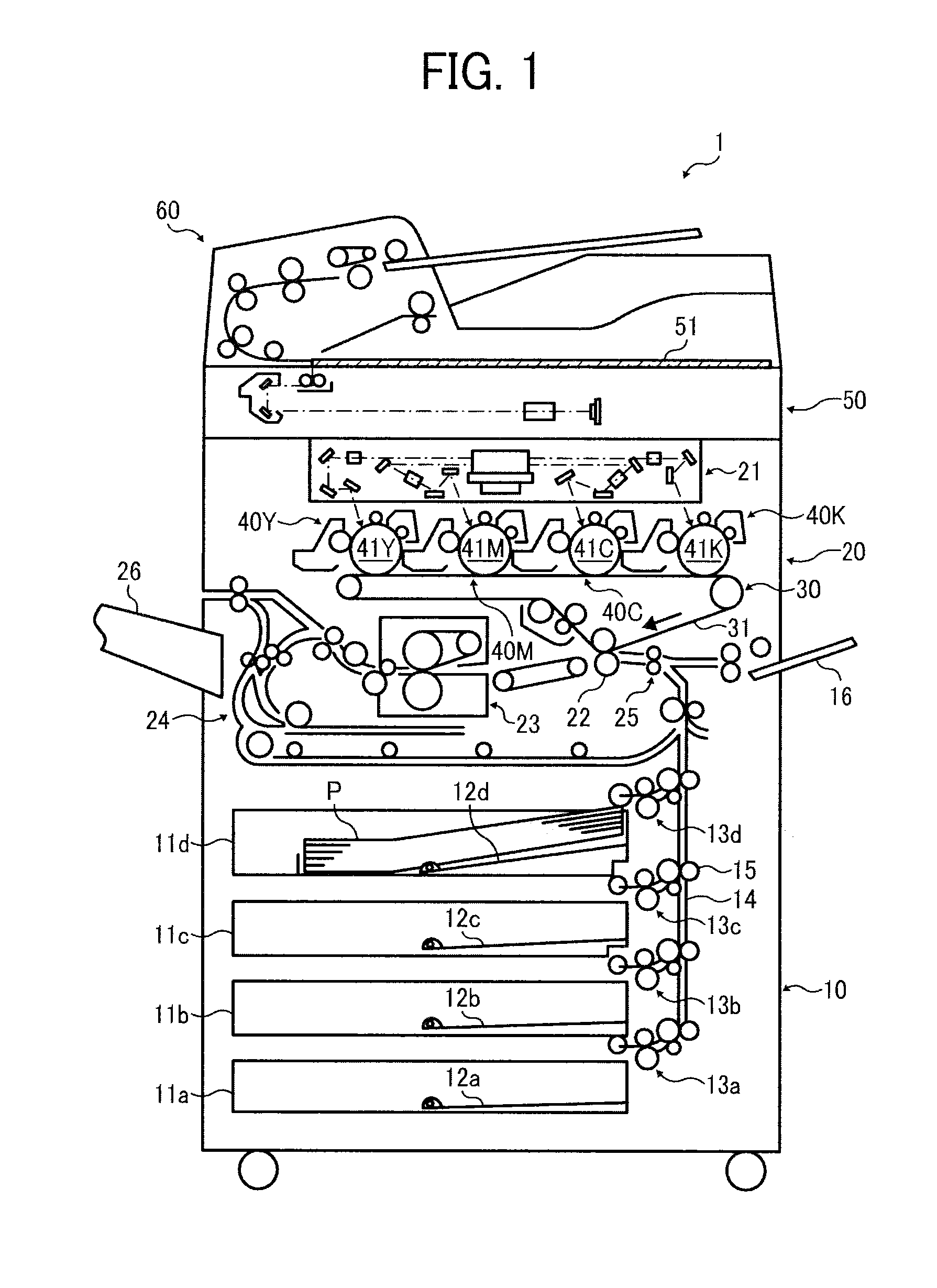
[0030]Referring now to the drawings, wherein like reference numerals designate identical or corresponding parts throughout the several views, particularly to FIGS. 1 through 11, a motor control device according to illustrative embodiments are described. It is to be noted that although the image forming apparatus of the present embodiment is described as a printer, the image forming apparatus of the present invention is not limited thereto. In addition, it is to be noted that the suffixes Y, M, C, and K attached to each reference numeral indicate only that components indicated thereby ar...


PUM


Abstract

A motor controller, operatively connected to a motor having an output shaft, includes a rotary detector to detect a rotation direction and a rotation amount of the output shaft of the motor to generate an actual rotary signal, a drive controller to generate a control signal based on the actual rotary signal and a target rotary signal indicating a target rotary direction and a target rotary amount, and a driver to supply a driving power to the motor based on the control signal. When the motor is in a hold state, the control signal is reversed periodically for a predetermined reverse time period T2 per a predetermined one reverse cycle T1. When the control signal is not reversed for a certain lock detection time period Tr that is longer than the revere cycle T1 of the control signal, supply of the driving power to the motor is blocked.

Description

CROSS-REFERENCE TO RELATED APPLICATION[0001]This patent application is based on and claims priority pursuant to 35 U.S.C. §119 to Japanese Patent Application No. 2012-175502, filed on Aug. 8, 2012 in the Japan Patent Office, the entire disclosure of which is hereby incorporated by reference herein.BACKGROUND[0002]1. Technical Field[0003]The present disclosure relates to a motor controller, an image processing apparatus including the motor controller, and a motor control method executed by the motor controller.[0004]2. Related Art[0005]With image readers contained in scanners, copiers, facsimiles, and multi-function devices, and image processing apparatus, such as image forming apparatuses, accuracy in reading and forming images is ensured by accurately operating relevant movable parts.[0006]For example, in a state in which a fixed image reader reads a document while a document feeder, such as an Auto Document Feeder (ADF), transports successive documents, a light source irradiates e...

Claims


Application Information

Patent Timeline
Patent Type & Authority Applications(United States)
IPC IPC(8): H02P6/00H02P6/06H02P6/08H02P6/12H02P6/17
CPCH02P6/003G05B19/042G05B2219/2646H02P6/30G03G15/6529G05B6/02
Inventor MURATA, TAKUYAISHIZUKA, NATSUKO
Owner RICOH KK
Why Eureka
Try Eureka