Train Platform Safety Device

Active Publication Date: 2014-02-20
SKD HI TEC +1
View PDF21 Cites 3 Cited by
  • Summary
  • Abstract
  • Description
  • Claims
  • Application Information

AI Technical Summary

Benefits of technology

[0022]A train platform safety device according to the present invention is installed at a position corresponding to a safety line on a subway or railway platform and is configured such that wire ropes are moved upwards or downwards depending on conditions in which a train approaches or departs from the platform, thus preventing a passenger from intentionally or unintentionally falling onto a trail track.
[0023]Particularly, the distances that the wire ropes move upwards or downwards are determined by rotating a rotating unit including rotating members having different diameters, whereby the wire ropes overlap each other or spread from each other. In this way, the wire ropes allow or block access of passengers depending on conditions in which a train approaches or departs from the platform, thus fundamentally prevent

Problems solved by technology

Therefore, accidents of passengers falling onto train tracks or colliding with trains that are entering the platforms frequently occur.
However, the yellow safety line merely functions to attract attention for safety such that passengers stand back behind the safety line, but the line itself cannot actually function to block a passenger from falling onto the train track or colliding with a train.
However, the conventional screen door is disadvantageous in that several tens of movable doors corresponding to doors of a train are required, thus increasing the production cost and initial installation cost.
As a result, the time it takes for passengers to exit and enter a train is increased, thus inconveniencing the passengers.
Particularly, in emergency situations, for example, when fire accidents occur in subways, if power is interrupted, the screen door cannot be operated.
In this case, the exits through which passengers can escape from the train are blocked, thus resulting in a tragic disaster.
Therefore, the screen door cannot be used in an existing subway system which has no ATO system.
Eventually, there ar

Method used


Image

  • Train Platform Safety Device
  • Train Platform Safety Device
  • Train Platform Safety Device

Examples


Example

BEST MODE

[0034]Hereinafter, the construction of the present invention will be described in detail with reference to the attached drawings.

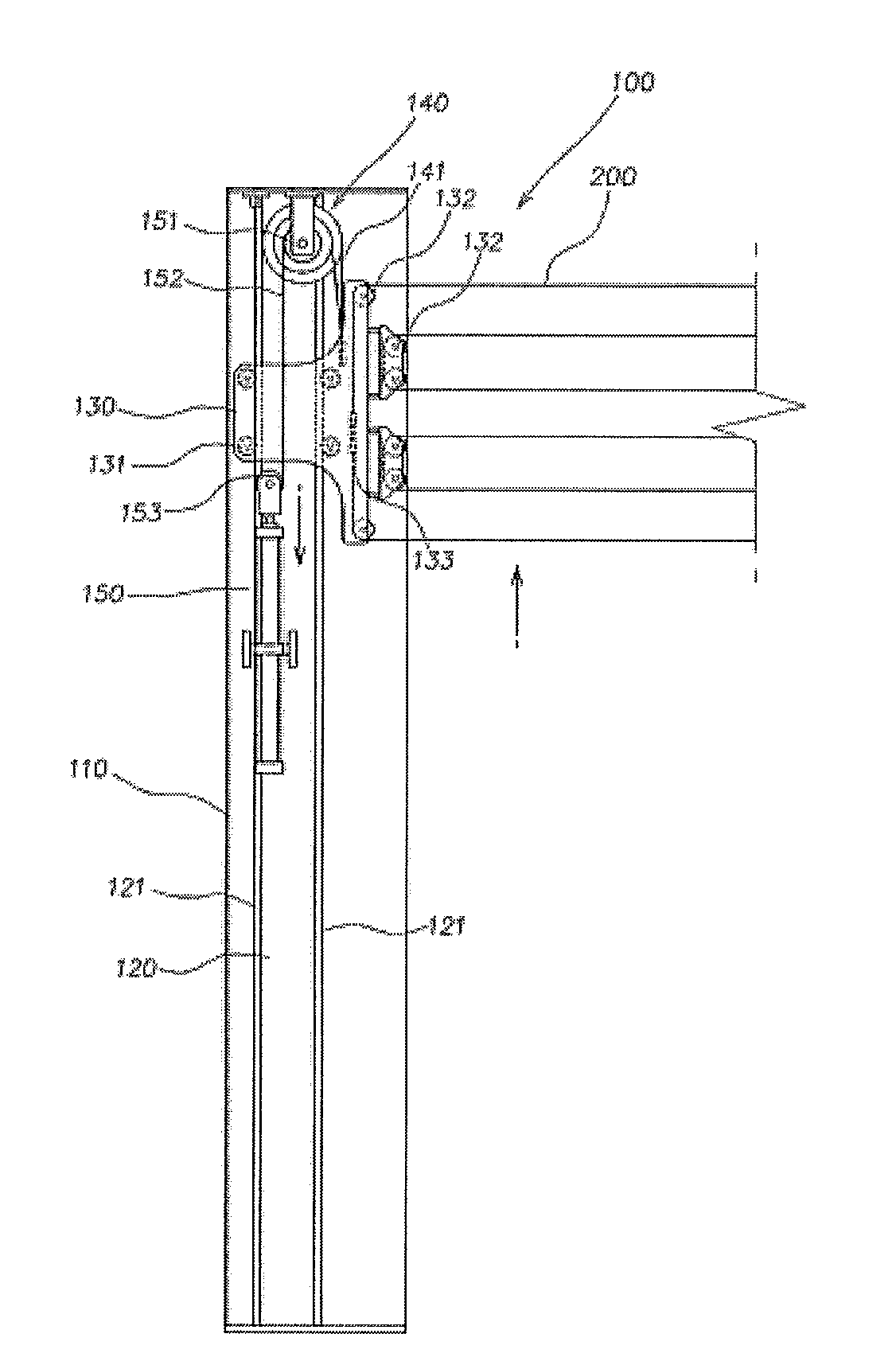
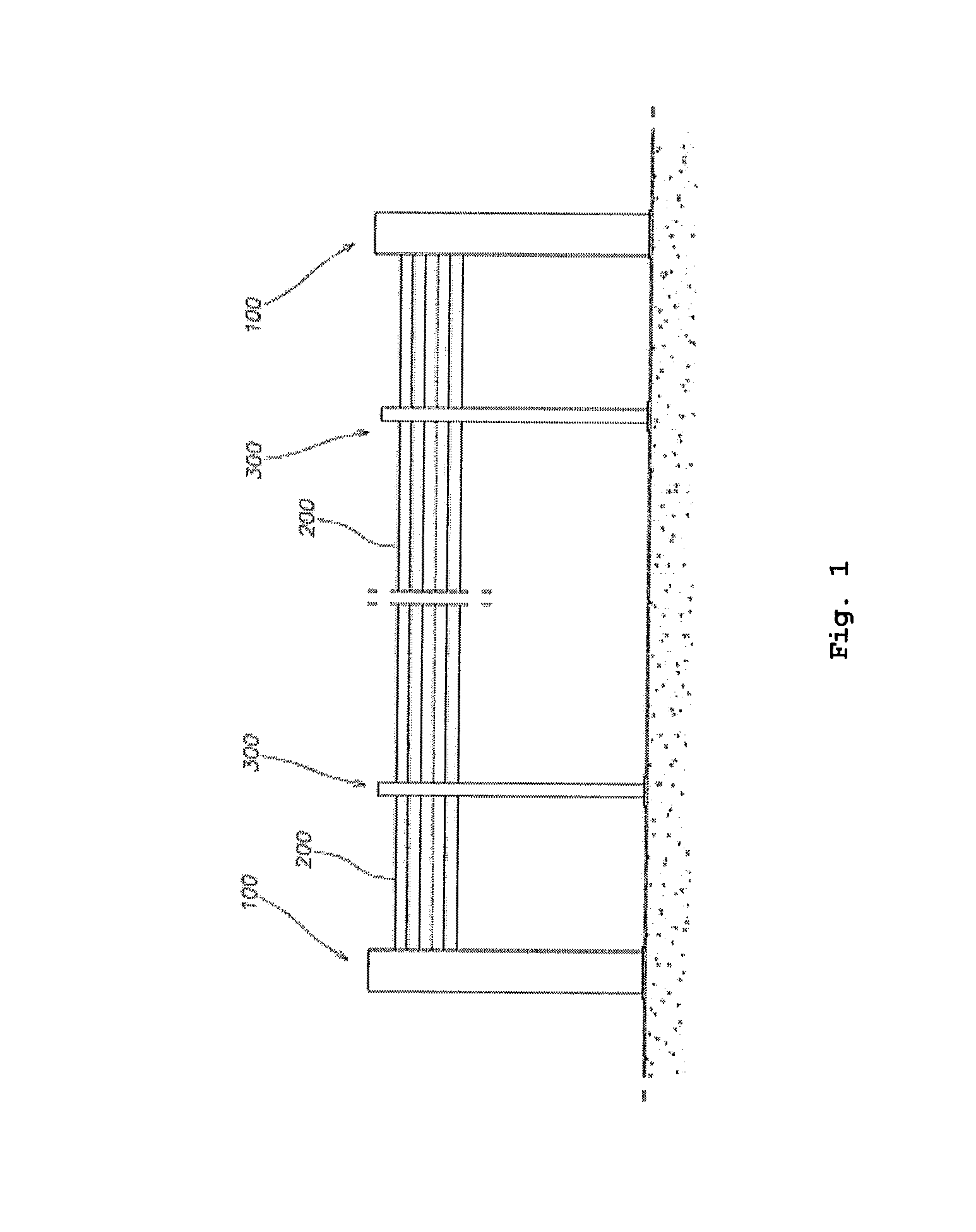
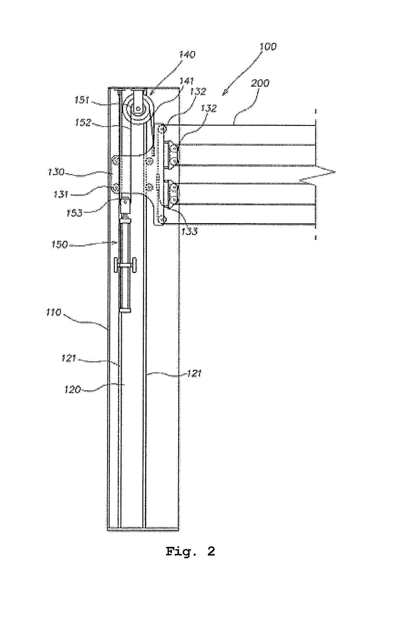
[0035]FIG. 2 is a front view illustrating the construction of a train platform safety device, according to the present invention. FIG. 3 is a plan view illustrating the construction of the train platform safety device, according to the present invention. FIGS. 4 through 6 are front views showing another embodiment of the train platform safety device according to the present invention. FIGS. 7 and 8 are front views illustrating the operation of the train platform safety device according to the present invention.

[0036]The train platform safety device according to the present invention includes: a plurality of wire rope lift units 100 which are installed at selected locations between an inlet of a platform through which a train enters the platform and an outlet of the platform and moves wire ropes 200 upwards or downwards; the wire ropes 200 which ar...


PUM


Abstract

Disclosed herein is a train platform safety device. The train platform safety device is installed at a position corresponding to a safety line on a subway or railway platform and is configured such that wire ropes are moved upwards or downwards depending on conditions in which a train approaches or departs from the platform, thus preventing a passenger from intentionally or unintentionally falling onto the train track. Particularly, the distances that the wire ropes move upwards or downwards are determined by rotating a rotating unit including rotating members having different diameters, whereby the wire ropes overlap each other or spread from each other. In this way, the wire ropes allow or block access of passengers depending on conditions in which a train approaches or departs from the platform, thus fundamentally preventing a safety accident.

Description

TECHNICAL FIELD[0001]The present invention relates, in general, to train platform safety devices and, more particularly, to a train platform safety device (referred to as a rope screen door, “RSD”) which is configured such that, as rotating members having different diameters are rotated, distances that a plurality of blocks to which wire ropes are connected are moved upwards or downwards are determined so that the wire ropes overlap each other or spread from each other, thus allowing or blocking access of passengers depending on conditions in which a train approaches or departs from the platform.BACKGROUND ART[0002]Generally, subway or railway platforms are open towards train tracks to allow passengers to board trains. Therefore, accidents of passengers falling onto train tracks or colliding with trains that are entering the platforms frequently occur. In an effort to overcome the above problems, a yellow safety line is marked on a platform to recommend passengers to stand behind wh...

Claims


Application Information

Patent Timeline
IPC IPC(8): B61B1/02
CPCB61B1/02E01F13/028E01F13/048E01F1/00
Inventor HAN, SEONG-MOO
Owner SKD HI TEC
Why Eureka
Try Eureka