
Safety device of blind cord

Inactive Publication Date: 2016-06-16
WINPLUS
View PDF31 Cites 8 Cited by
  • Summary
  • Abstract
  • Description
  • Claims
  • Application Information

AI Technical Summary

Benefits of technology

The present invention proposes a safety device for blind cords that can only be used when attached to a wall, to prevent accidents and especially the entanglement of babies or young children. The device includes a housing and a pressure slider that moves along with the blind cord. The more the blind cord is pulled, the more securely it is locked to the wall, while the housing remains easily gripable. This results in a safer and more secure use of blinds.

Problems solved by technology

However, the blind cords used to control the positions of the blinds may cause safety accidents, particularly for a baby or young child who may get the blind cords caught around his or her neck or ankle.
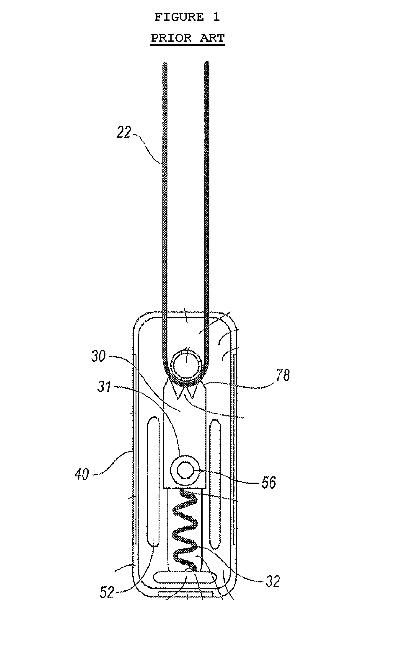
However, the looped-cord tensioner of the related art is problematic in that the looped-cord 22 may undesirably move by a user's continuous manipulation due to a pressure decline, wherein the pressure decline arises because the slide member 30 presses a single portion of the looped-cord 22.
The loop cord tension device according to the related art is problematic in that it is difficult to grip the holed sleeve, which makes it difficult to attach the slide member to a wall.

Method used


Image

  • Safety device of blind cord
  • Safety device of blind cord
  • Safety device of blind cord

Examples


first embodiment

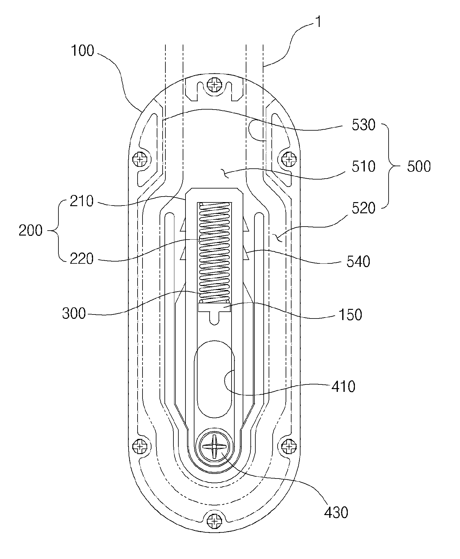
[0068]According to the present invention, the resilient member 300 is a compression coil spring. However, the resilient member 300 may be a tension coil spring or a spiral spring so as to provide resilience via movement of the pressure slider 200 or the housing 100.

[0069]Meanwhile, as shown in FIG. 4, the pressure slider 200 according to the first embodiment of the present invention may include a towing sleeve 420 mentioned hereinafter that is provided in a lower part of the slider main body 210. Thereby, as shown in FIGS. 5 and 6, the slider main body 210 can move.

second embodiment

[0070]Further, as shown in FIGS. 7 and 8, the pressure slider 200 according to the present invention may be configured such that the housing 100 moves without the towing sleeve 420.

[0071]The attachment unit 400 attaches the pressure slider 200 or the housing 100 to a wall in the state where the resilient member 300 is pressed via movement of the pressure slider 200 or the housing 100 as mentioned hereinbefore.

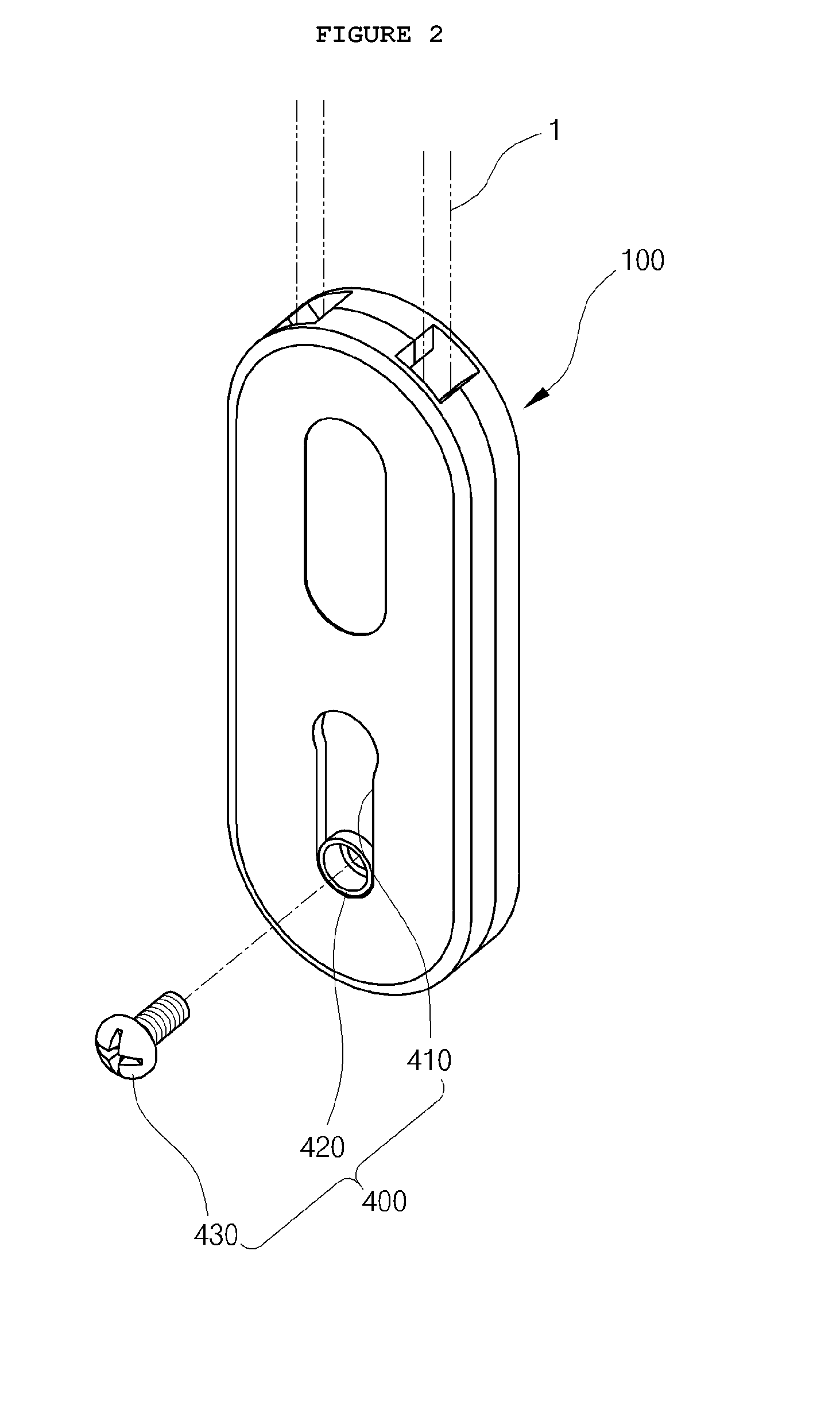
[0072]For example, as shown in FIG. 3, the attachment unit 400 according to the first embodiment of the present invention may include a guide slot 410, the towing sleeve 420, and a locking bolt 430.

[0073]As shown in FIG. 3, the longitudinal guide slot 410 is provided in the housing 100, and guides movement of the towing sleeve 420 provided in the pressure slider 200, exposing the towing sleeve 420.

[0074]As shown in FIG. 3, the tubular towing sleeve 420 penetrates through a lower part of the pressure slider 200, and is exposed via the guide slot 410.

[0075]The towing sleeve 420 p...


PUM


Abstract

Disclosed is a safety device of a blind cord. The safety device is configured to allow a blind cord to perform a normal function only when the blind cord that is used to control a position of a blind, such as the vertical or horizontal position of the blind, or an angle of the blind, is attached to a wall, whereby it is possible to prevent a safety accident, in particular, to prevent a baby or young child from being caught in the blind cord. The safety device allows a normal function of the blind cord only when a lower portion of the blind cord is locked to a wall via the housing, thereby preventing the blind cord from undesirably moving. Therefore, it is possible to prevent a safety accident, in particular, to prevent a baby or young child from being caught in the blind cord that undesirably moves.

Description

CROSS REFERENCE TO RELATED APPLICATION[0001]The present application claims priority to Korean Patent Application No. KR 2014-0181401, filed Dec. 16, 2014, the entire contents of which is incorporated herein for all purposes by this reference.BACKGROUND OF THE INVENTION[0002]1. Field of the Invention[0003]The present invention generally relates to a safety device of a blind cord. More particularly, the present invention relates to a safety device of a blind cord that is configured to allow a blind cord to perform a normal function only when the blind cord used to control a position of a blind, such the vertical and horizontal position of the blind, or an angle of the blind, is attached to a wall, whereby it is possible to prevent safety accident, in particular, to prevent a baby or young child from being caught in the blind cord.[0004]2. Description of the Related Art[0005]Generally, a blind as an interior decoration is installed in a window or an entrance of a building, and is used ...

Claims


Application Information

Patent Timeline
IPC IPC(8): E06B9/324
CPCE06B9/324E06B9/326E06B2009/3265E06B9/38E06B9/80E06B2009/801
Inventor BYUN, TAE-WOONG
Owner WINPLUS
Learn More