
Method of detecting integrity index of machine tool

Pending Publication Date: 2021-11-04
ITS
View PDF0 Cites 0 Cited by
  • Summary
  • Abstract
  • Description
  • Claims
  • Application Information

AI Technical Summary

Benefits of technology

The patent describes a method for detecting the integrity of a machine tool by measuring the power consumed by the machine in a normal state and a worn state. This data is used to create a reference table for the machine tool, which is then applied to real-time measurements to provide an integrity index value. This allows the machine tool to be managed actively and stably, preventing accidents or economic loss. Additionally, the method can detect the number of times the machine exceeds a warning or critical value, resulting in a more accurate measure of the machine tool's integrity.

Problems solved by technology

Since the tools for workpieces are gradually worn when they are used, when the performance (function) is deteriorated after they are used for a predetermined period, they are replaced with new tools.
Accordingly, although a toll can be sufficiently used more, the tool is replaced in advance in consideration of a large economic loss that may be generated by possible damage or breakage of the tool, so there is a problem that the tool is not efficiently replaced and managed.

Method used


Image

  • Method of detecting integrity index of machine tool
  • Method of detecting integrity index of machine tool
  • Method of detecting integrity index of machine tool

Examples


Embodiment Construction

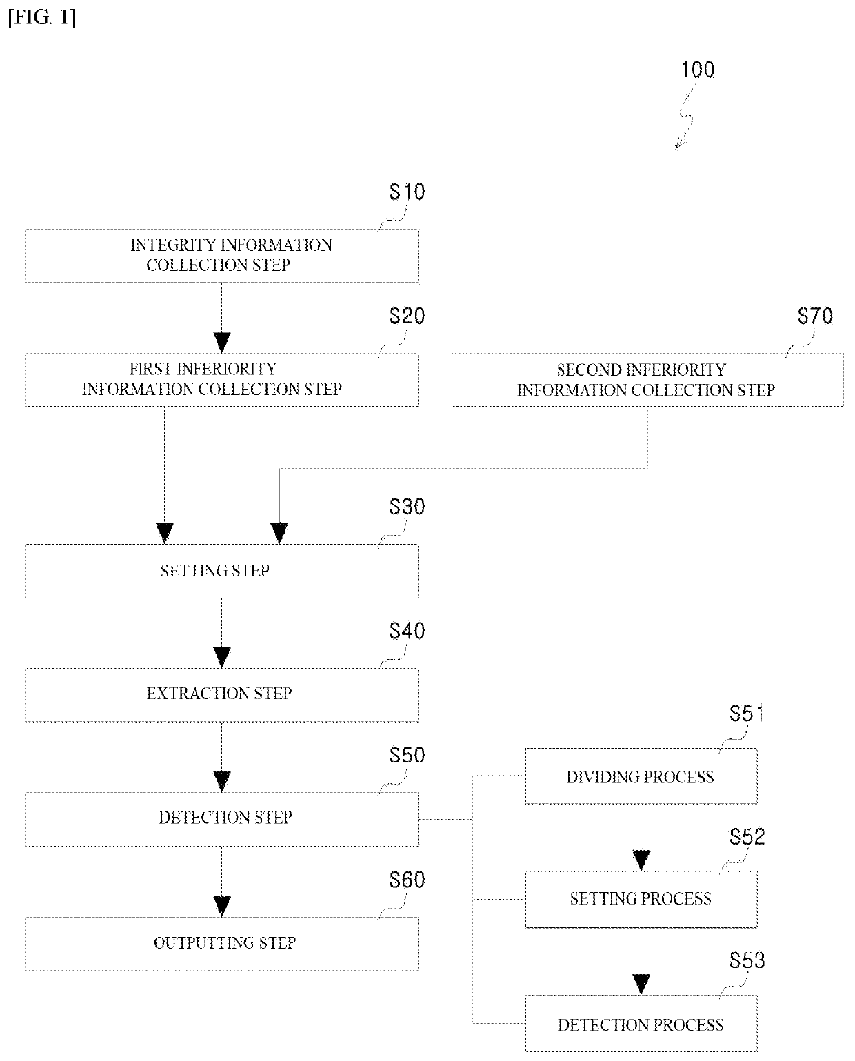
[0032]The integrity information collection step S10 of FIG. 1 is a step of collecting a current amount, which is consumed when a machine tool machines a workpiece in a normal state, in accordance with lapse of time.

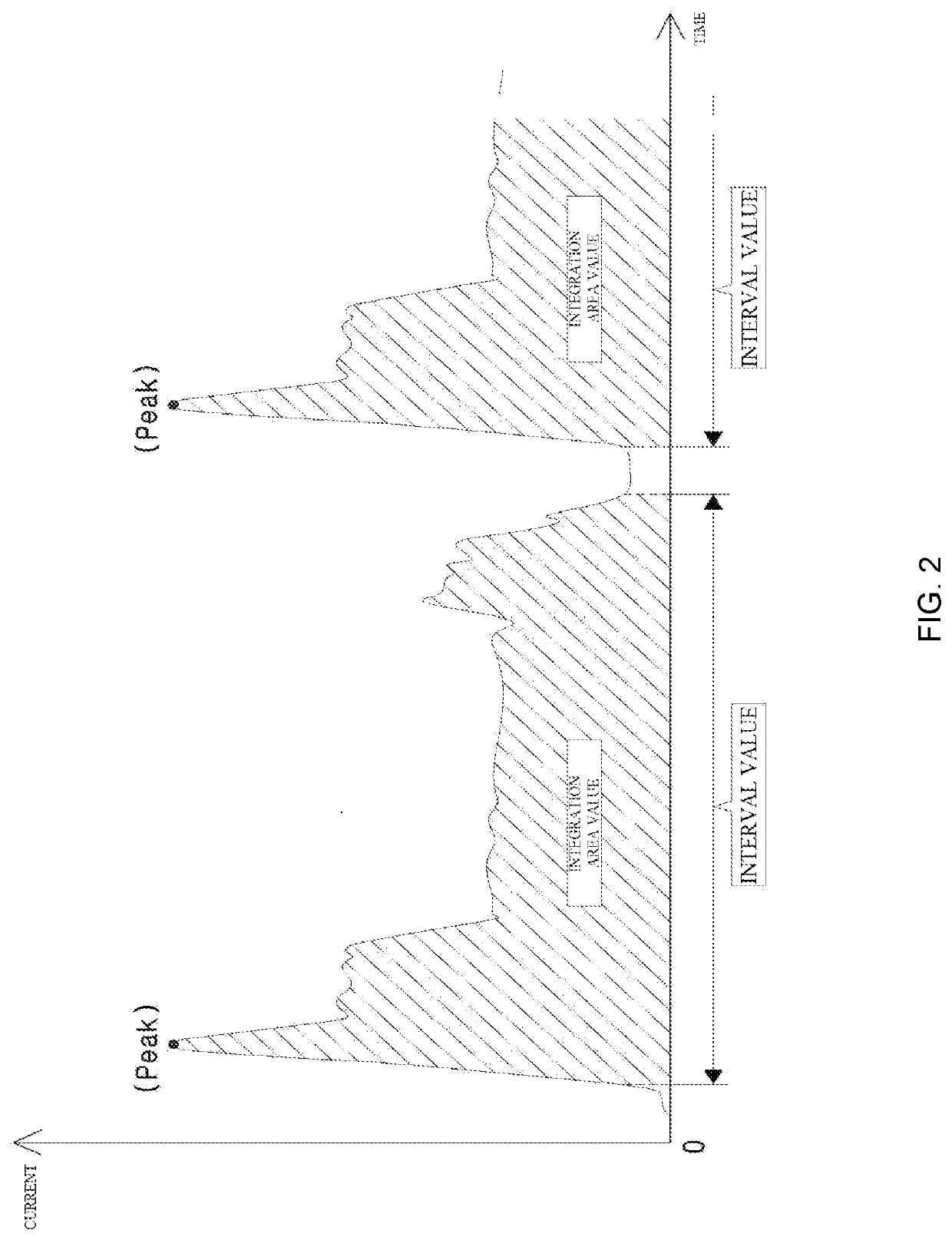
[0033]FIG. 2 shows a current amount (power information) according to time in a machine with a machine tool in a normal state.

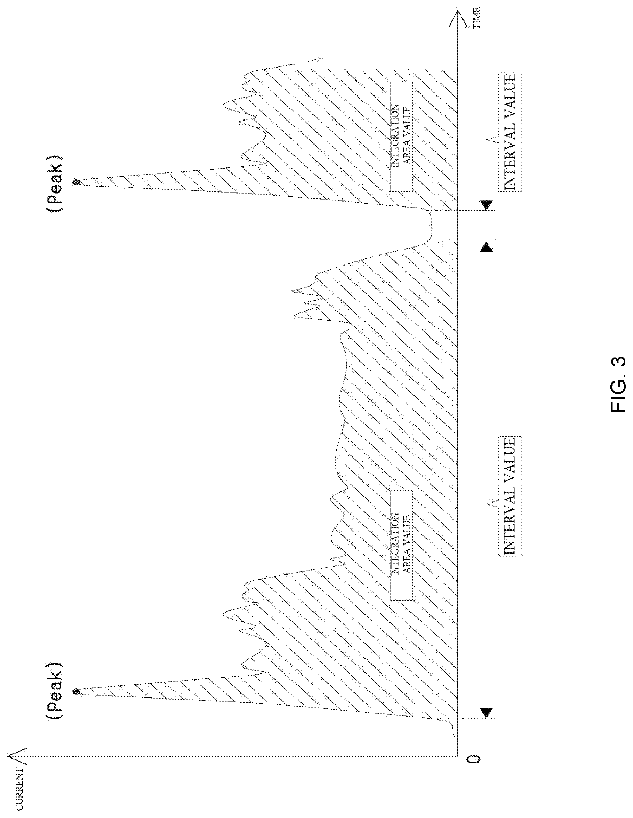
[0034]Referring to FIG. 2, it is possible to extract and collect a peak current value, an integration area value, and a machining interval value of a workpiece from power information.

[0035]The collected extraction values (the peak current value, the integration area value, and the interval value) are the base of the integrity reference value that is set to detect the integrity of the machine tool in the setting step S30 to be described below.

[0036]The peak current value means a value at which the magnitude of a current value is the peak in the information of power that is consumed by the machine.

[0037]The first inferiority information collection ste...


PUM


Abstract

The method of the present invention includes: an integrity information collection step of collecting a current amount; a first inferiority information collection step of collecting a current amount; a setting step of setting an integrity reference value and an inferiority reference value on the basis of the information collected; an extraction step of collecting a current amount in real time, and extracting a measurement value from the collected information; a detection step of detecting an integrity index value of the machine tool by comparing the measurement value extracted with the integrity reference value and the inferiority reference value set in the setting step; and an outputting step of outputting the integrity index value detected.

Description

CROSS-REFERENCE TO RELATED APPLICATIONS[0001]The present application is a bypass continuation application of currently pending international application No. PCT / KR2019 / 014522 having an international filing date of Oct. 31, 2019 and designating the United States, the international application claiming a priority date of Dec. 27, 2018 based upon prior filed K.R patent application No. 10-2018-0171365, the entire contents of the aforesaid international application and the aforesaid K.R. patent application being incorporated herein by reference.TECHNICAL FIELD[0002]The present invention relates to a method of detecting an integrity index of a machine tool and, more particularly, to a method of detecting an integrity index of a machine tool, the method: collecting the information of power that is consumed by a machine with a machine tool in a normal state and the information of power that is consumed by the machine with the machine tool in a worn state: constructing an integrity index ref...

Claims


Application Information

Patent Timeline
IPC IPC(8): B23Q17/09
CPCB23Q17/0995B23Q17/0957B23Q17/0961G05B19/4065
Inventor LEE, YOUNG KYU
Owner ITS
Learn More