Vacuum electron power tube

a vacuum electron and power tube technology, applied in the direction of discharge tube/lamp details, single discharge path tube, discharge tube with electrostatic control, etc., can solve the problems of bulky and complicated practi

Inactive Publication Date: 2014-02-20
BALDWIN DAVID A +1
View PDF9 Cites 6 Cited by
  • Summary
  • Abstract
  • Description
  • Claims
  • Application Information

AI Technical Summary

Benefits of technology

[0008]The details of one or more implementations are set forth in the accompanying drawings and the descrip...

Problems solved by technology

This practice may ...

Method used


Image

  • Vacuum electron power tube
  • Vacuum electron power tube
  • Vacuum electron power tube

Examples


example implementation

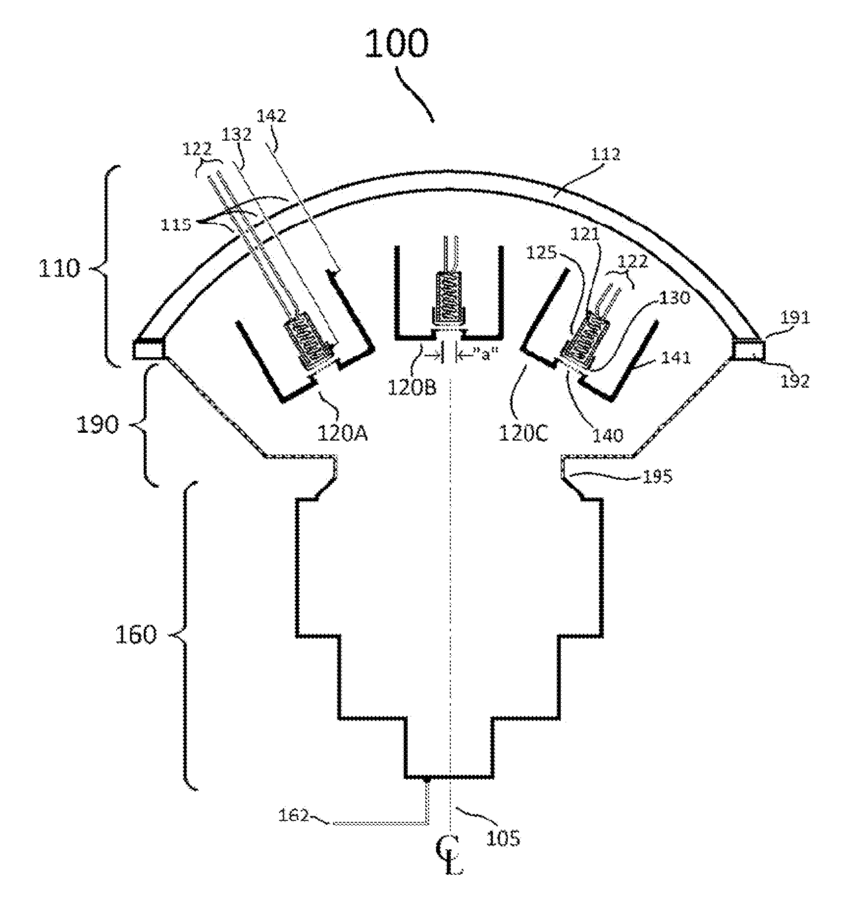
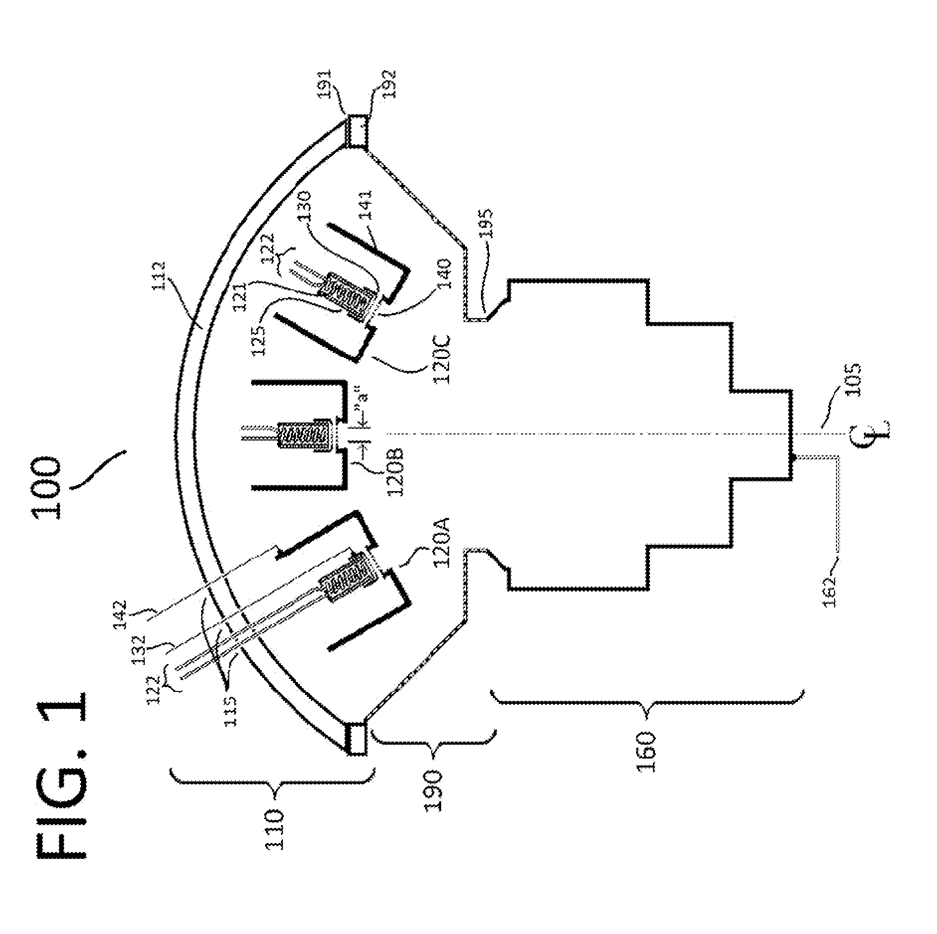
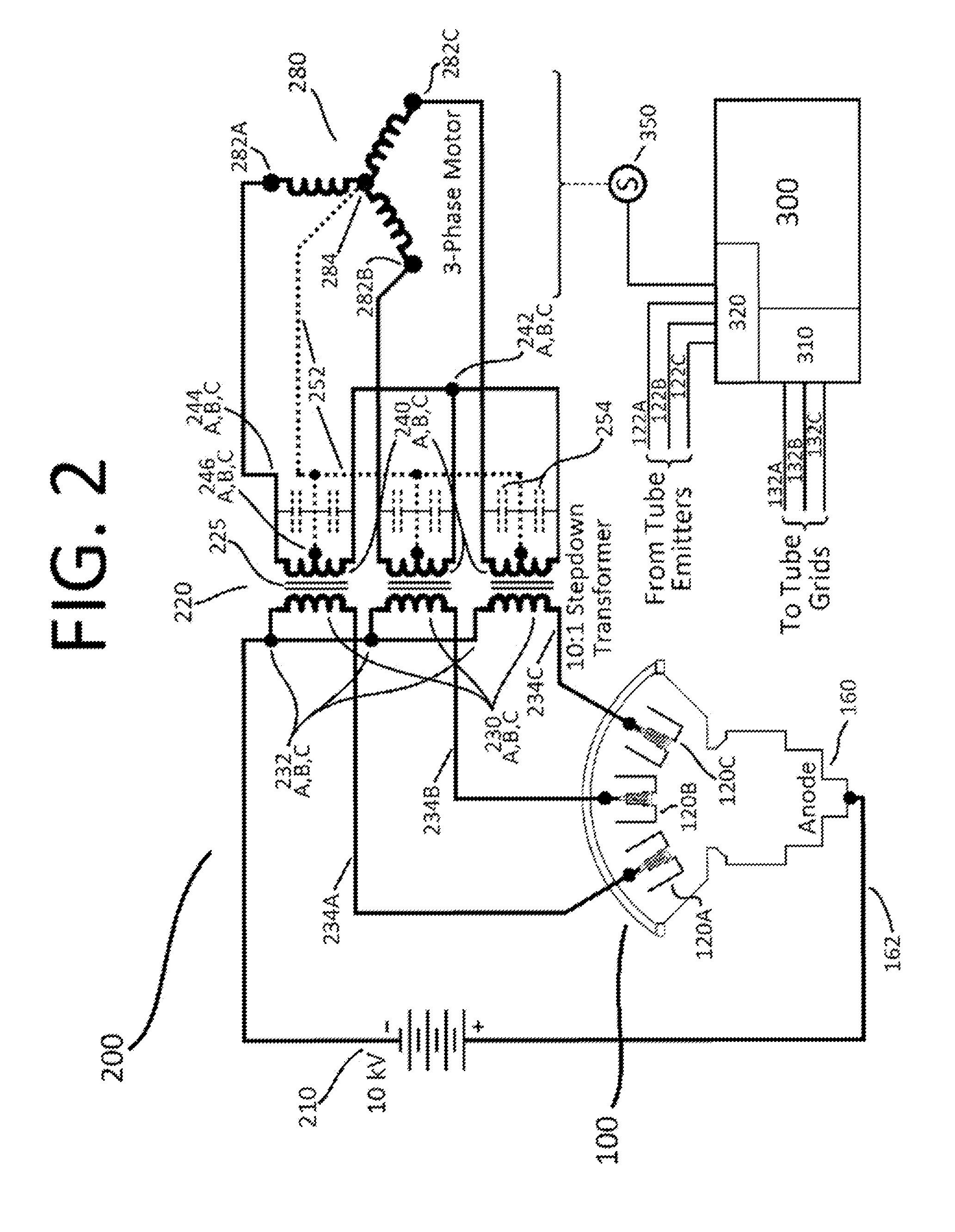
[0042]FIG. 4 is a simplified line drawing of one example implementation of a cylindrically symmetric electron tube comprising one common cathode emitter source and three anode structures or plates. Thus FIG. 4 depicts a multi-channel vacuum tube of the disclosure wherein the first electrode may include a cathode, wherein the second electrode may include a first anode, and wherein the third electrode may include a second anode, and further wherein a fourth electrode may include a third anode. In FIG. 4, only a mechanical concept schematic of the principal electrodes is given, omitting the vacuum envelope and construction details, which may be similar to standard vacuum tubes. Likewise, the principal electrical topology involving the tube's electrodes as shown in FIG. 2 are omitted, but an electrical source 210 may be present but with its negative terminal connected to the cathode-emitter electron source 120; the three anodes may be connected through three loads, also not shown, back ...


PUM


Abstract

A vacuum tube that may include but is not limited to a plurality of electrodes. A first electrode of the plurality of electrodes may be configured to operatively connect to an electrical source. A second electrode of the plurality of electrodes may be configured to operatively connect to a first load of a plurality of loads, wherein the first electrode may be configured to complete a first circuit through the second electrode and the first load. A third electrode of the plurality of electrodes may be configured to operatively connect to a second load of the plurality of loads that is independent from the first load, wherein the first electrode may be configured to complete a second circuit through the third electrode and the second load.

Description

RELATED CASES[0001]This application claims the benefit of U.S. Provisional Application No. 61 / 682,977, filed on 14 Aug. 2012, by Baldwin et al., entitled Vacuum electron power tube with three output channels or three-phase output, the contents of which is all incorporated by reference.BACKGROUND[0002]Vacuum electron tubes and various types of grid-controlled emitters of electrons may be known. Historically, such devices may have included, e.g., a single electron emitter and a single electron collector along with zero, one, two or more additional electrodes which may serve to turn on, turn off or variably influence or control the flow of electron current from the emitter to the collector. An “emitter” may also be called a cathode, an electron gun, a thermionic emitter, or a field emitter, among other names. A “collector” may also be called an anode, or a plate, among other names.[0003]A single electrical power source may be used to supply multiple electrical devices or loads. When mo...

Claims


Application Information

Patent Timeline
IPC IPC(8): H01J21/20H01J21/26
CPCH01J21/26H01J21/20H02P27/06
Inventor BALDWIN, DAVID A.BROWN, KEVIN L.
Owner BALDWIN DAVID A
Why Eureka
Try Eureka