

Multichannel RF volume resonator for MRI
a multi-channel, volume resonator technology, applied in the direction of instruments, magnetic measurements, measurement devices, etc., can solve the problem of complex tuning procedur
- Summary
- Abstract
- Description
- Claims
- Application Information
AI Technical Summary
Benefits of technology
Problems solved by technology
Method used
Image

Examples
first embodiment
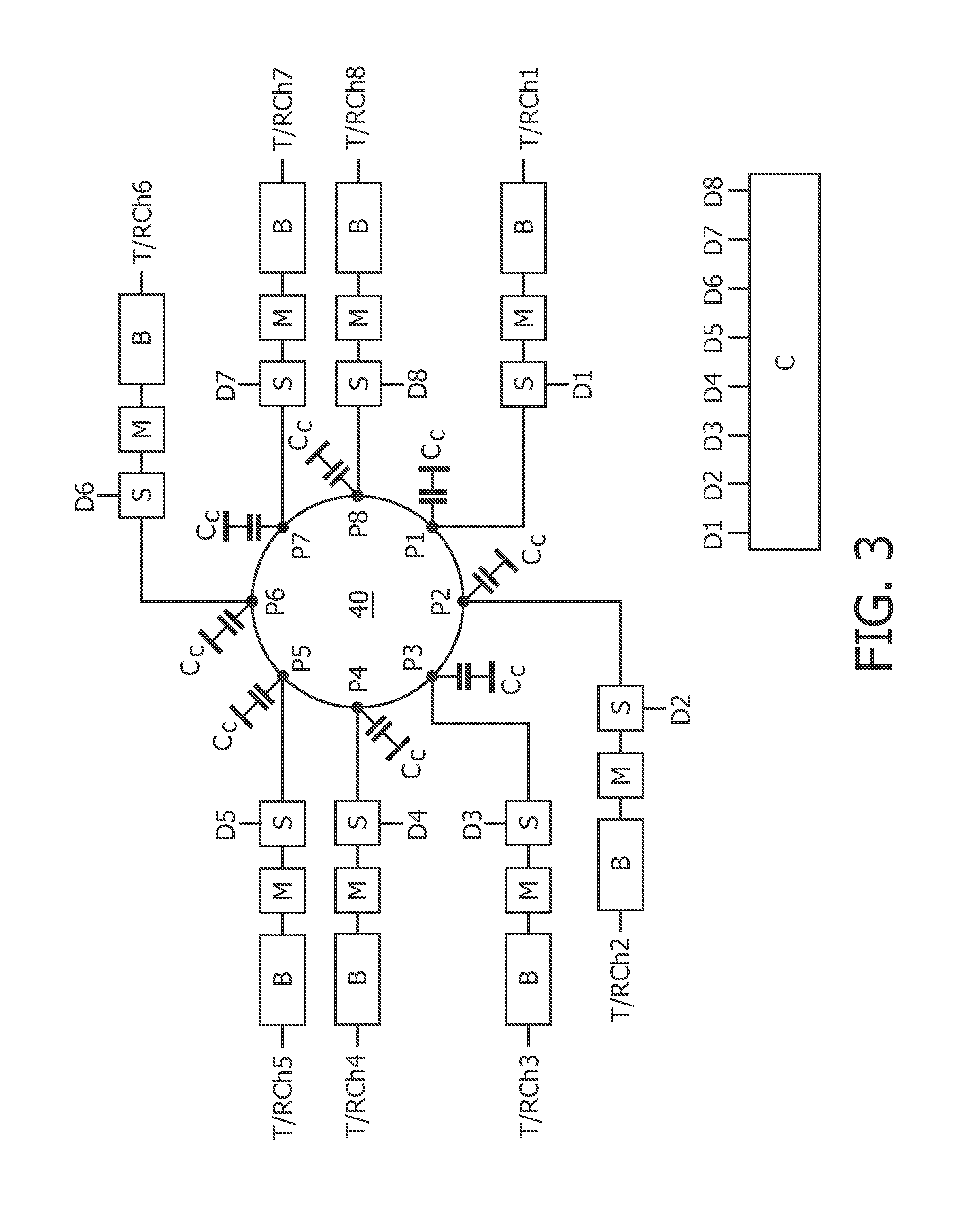
[0051]FIG. 3 schematically shows substantial components of such an RF volume resonator system according to the invention. It comprises a multi-port RF volume resonator preferably comprising a first and a second planar multi-port RF antenna 40, 50 each in the form of a planar electrically conductive plate (only the first planar RF antenna 40 is shown) with a plurality of ports P1, . . . Pn with which each a transmit or receive channel T / RCh is connected.
[0052]The first (and the second) planar multi-port RF antenna 40 is / are preferably provided in the form of each a circular plate which is connected via capacitors Cc to a ground potential in a known manner. The plate can also have an oval or a polyangular or another shape. Along the circumference of the plate, the ports P1, . . . P8 are located, wherein in case of the embodiment shown in FIG. 3 adjacent ports have the same distances in the circumferential direction from each other. However, as mentioned above, these distances can also...
fourth embodiment
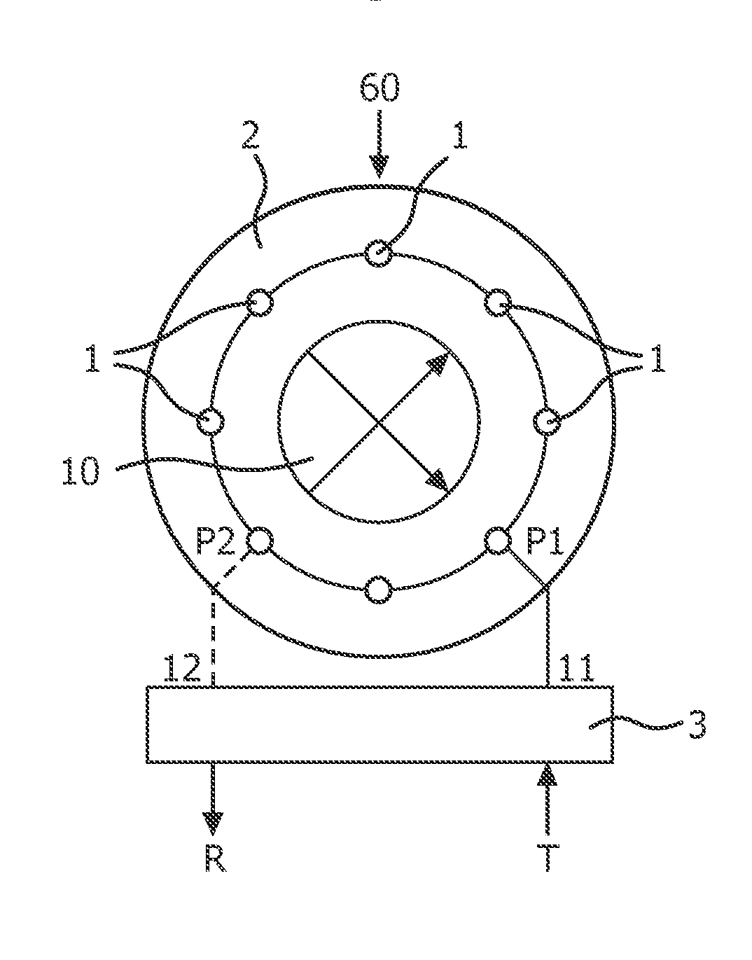
[0071]FIG. 6 shows a schematic three-dimensional view of an RF volume resonator system, again comprising a multi-port birdcage coil 60, which has an at least substantially circular cross section. Further, additionally to the ports P1, P3, P4 and Pn which are arranged at and along the first end conductor 2, one port P2 is exemplarily indicated at one of the rungs 1 of the birdcage coil.
[0072]In contrary to the embodiments shown in FIGS. 3 and 4, the third and fourth embodiment of the RF volume resonator system according to FIGS. 5 and 6, respectively, is provided with transmit and receive channels at each port P1, . . . Pn. For connecting each port either with a power amplifier for transmitting RF signals or with a low noise amplifier for processing received MR signals, each a transmit / receive switch T / R is provided which is connected exemplarily between the matching circuit M and the related amplifiers. However, also the embodiments shown in FIGS. 3 and 4 can be provided with such t...
fifth embodiment
[0075]FIG. 7 shows an RF volume resonator system. Substantially, only the differences to the above embodiments shall be explained.
[0076]This RF resonator system comprises a multi-port RF resonator according to the invention in the form of a birdcage coil which instead of the rungs as indicated in FIGS. 5 and 6 is provided with strip lines 1 as defined above. FIG. 7 shows a part of a related conductor structure 60 schematically unrolled into the two dimensional plane.
[0077]Further, FIG. 7 schematically indicates the first and the second end conductor 2, 3 between which the strip lines 1 extend. The strip lines 1 are coupled at both their ends by means of coupling capacitors CR to the first and the second end conductor 2, 3, respectively. Further, the end conductors 2, 3 comprise capacitors CT which are serially connected into the end conductors 2, 3 for tuning the spectrum of the resonant modes of the RF coil as generally known.
[0078]Preferably at one of the ends of each strip line 1...
PUM
 Abstract
Description
Claims
Application Information