Chain drive for saddle-ride type vehicle

Active Publication Date: 2014-03-06
HONDA MOTOR CO LTD
View PDF0 Cites 15 Cited by
  • Summary
  • Abstract
  • Description
  • Claims
  • Application Information

AI Technical Summary

Benefits of technology

[0011]Since the cylindrical guide is mounted coaxially with the engine hanger bolt that is located in a direction rearwardly in the vehicle-body longitudinal direction and upwardly of the drive sprocket and extends in the vehicle width direction, excessive displacement of the drive chain can be restricted by the guide tube having a simple structure, and the guide tube can be easily mounted to the body frame without setting a special mounting portion on the body frame. Therefore, the present invention allows the protection of on-vehicle equipment and lower production costs.
[0012]In accordance with another aspect of the invention, the chain drive for the saddle-ride type vehicle further includes an auxiliary guide member at a position spaced rearwardly in the vehicle-body longitudinal direction of the guide tube. The auxiliary guide member restricts upward displacement of the drive chain. Thus, the excessive upward displacement of the drive chain can be more reliably restricted.
[0013]In further accordance with the present invention, the auxiliary guide member has a cylindrical shape and is fixed to a shaft protruding from the body frame by a retaining pin, thereby allowing lower production costs.
[0014]In further accordance with the present invention, a chain drive for a saddle-ride type vehicle includes a body frame, an air cleaner, a drive sprocket, a swing arm, a driven sprocket, a drive chain, an engine hanger bolt, a cylindrical guide tube, and an auxiliary guide member. The body frame includes a head pipe; a main frame pipe extending rearward from the head pipe; left and right center pipes extending downward from a rear portion of the main frame pipe; left and right seat rails extending rearward from a rear portion of the main frame pipe; and left and right support pipes each coupling together a lower area of the center pipes and a rear area of the seat rails. The air cleaner is installed in a space surrounded by the center pipes, the seat rails, and the support pipes in side view. The air cleaner filters air drawn into an engine. The drive sprocket is mounted to an output shaft of an engine block. The swing arm has front and rear portions, the front portion of the swing arm being disposed between the left and right center pipes and swingably supported by the left and right center p

Problems solved by technology

The large up-and-down movement of the drive chain during traveling of the vehicle makes the drive chain more likely to interfere with the surroundings.
However, in the above-described chain drive, because the special U-section guide member

Method used


Image

  • Chain drive for saddle-ride type vehicle
  • Chain drive for saddle-ride type vehicle
  • Chain drive for saddle-ride type vehicle

Examples


Embodiment Construction

[0029]Hereinafter, an embodiment of the present invention will be described with reference to the accompanying drawings. It is to be noted that references to directions, such as front, rear, left, and right, in the following description are made with reference to a vehicle, unless otherwise stated. It is also to be noted that, in the drawings, arrow FR indicates the front of the vehicle, arrow UP indicates the upper side of the vehicle, and arrow LH indicates the left of the vehicle.

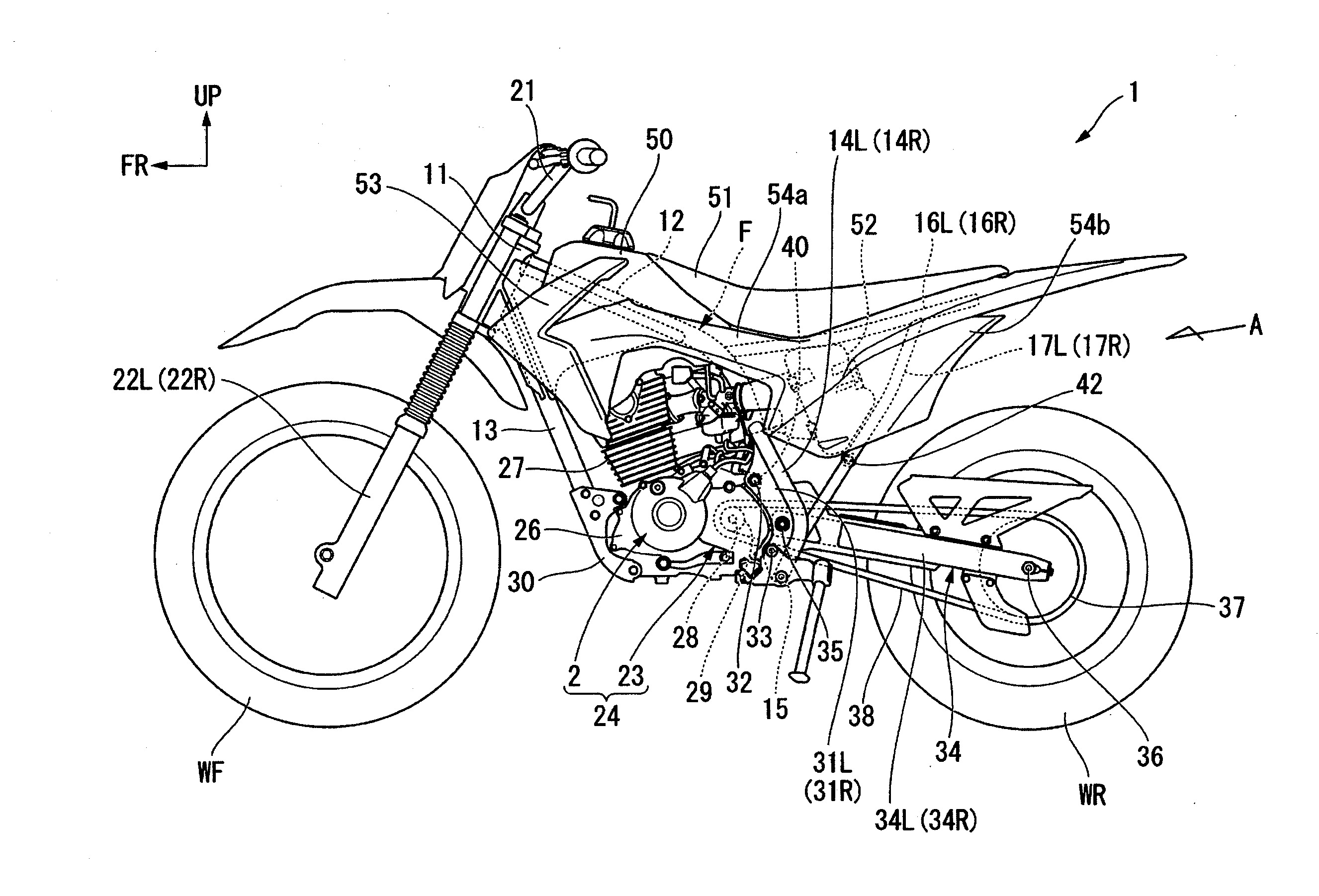
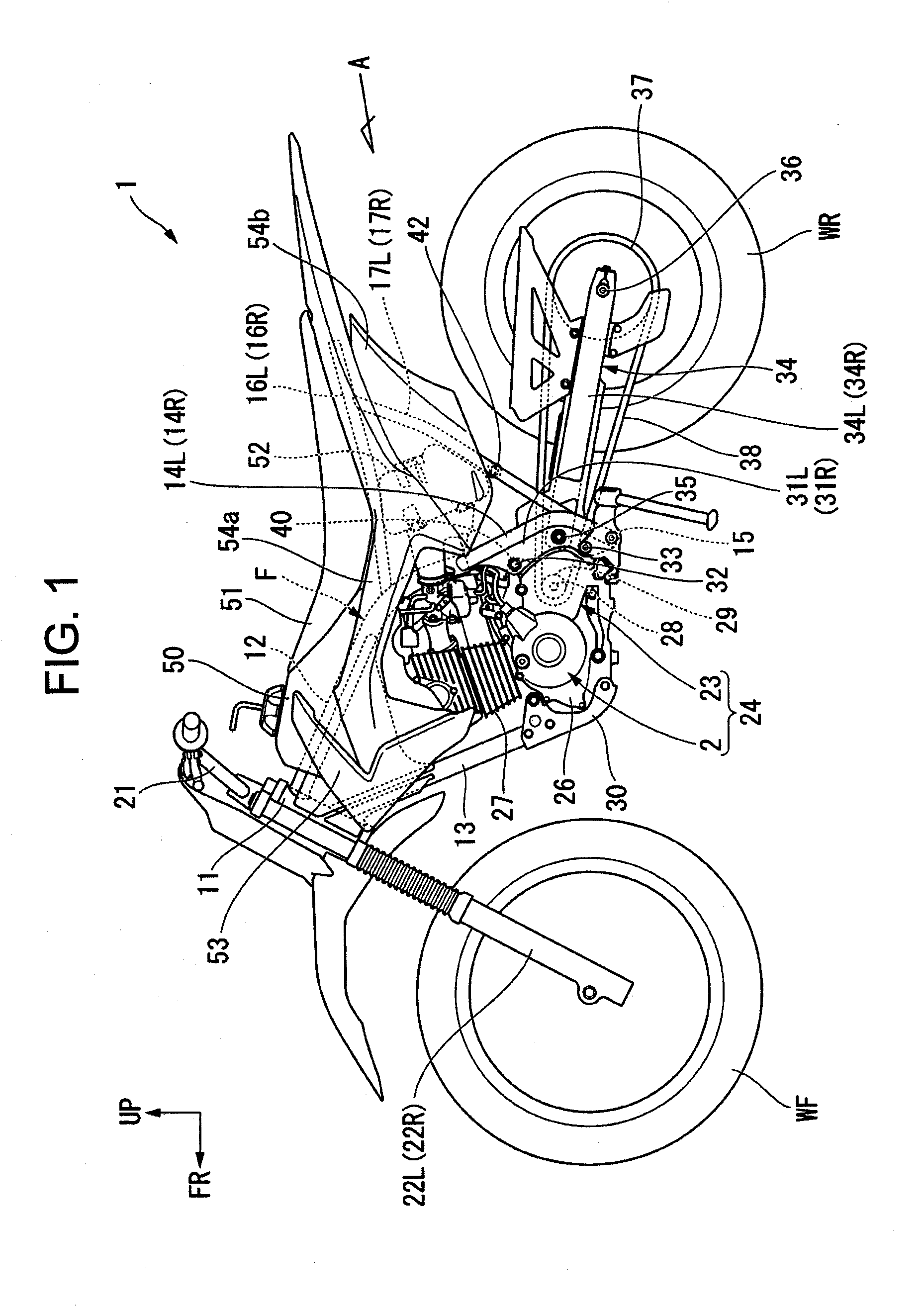
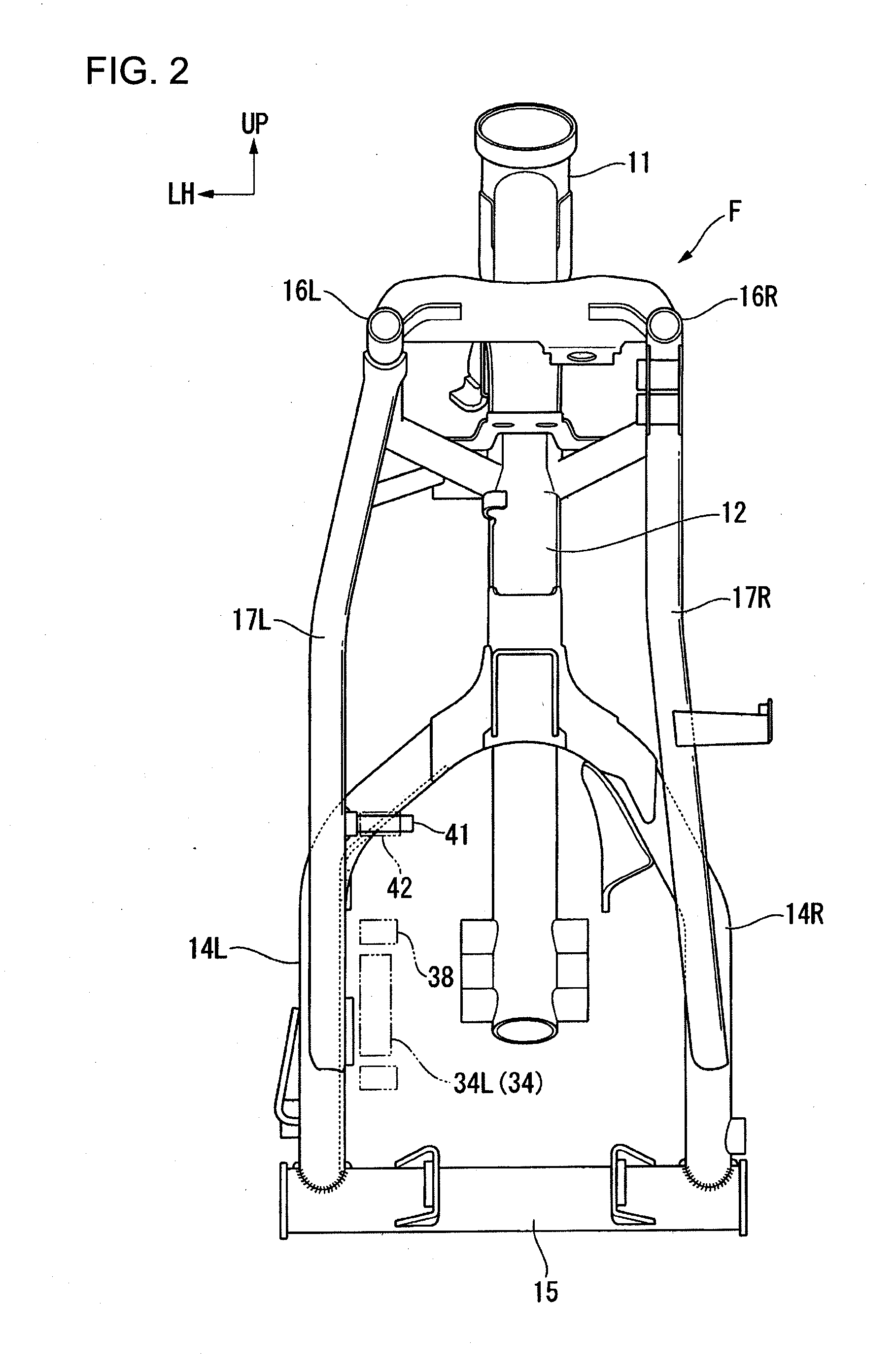
[0030]FIG. 1 is a general side view of a saddle-ride type vehicle according to this embodiment, and FIG. 2 is a view of a body frame F of the saddle-ride type vehicle, viewed in the direction of the arrow A in FIG. 1.

[0031]The saddle-ride type vehicle according to this embodiment is an off-road motorcycle in which a rear wheel WR is driven by an engine 2. Hereinafter, the saddle-ride type vehicle according to this embodiment is referred to as “motorcycle 1”.

[0032]The body frame F of the motorcycle 1 incl...


PUM


Abstract

A chain drive is provided with an engine hanger bolt. The engine hanger bolt is located in a direction rearwardly in a vehicle-body longitudinal direction and upwardly of a drive sprocket and extends in a vehicle width direction to fix an engine block to a body frame. A guide tube is mounted coaxially with the engine hanger bolt and restricts upward displacement of a drive chain.

Description

BACKGROUND OF THE INVENTION[0001]1. Field of the Invention[0002]The present invention relates to a chain drive for a saddle-ride type vehicle in which power of an engine is transmitted to a rear wheel through a drive chain.[0003]2. Description of Related Art[0004]In this type of saddle-ride type vehicle, it is known that the tension on a drive chain varies due to the impact when the vehicle travels on a rough road or accelerates / decelerates. Especially in saddle-ride type vehicles in which a rear wheel is supported by a body frame through a swing arm, the variations in tension of the drive chain coupled with the swing of the swing arm make the drive chain likely to move up and down largely. The large up-and-down movement of the drive chain during traveling of the vehicle makes the drive chain more likely to interfere with the surroundings.[0005]Therefore, as a chain drive for saddle-ride type vehicles which addresses this problem, there is known a chain drive in which a guide member...

Claims


Application Information

Patent Timeline
IPC IPC(8): B62K11/04B62K11/00
CPCB62K11/00B62K11/04B62J13/00B62M7/00F16H7/18
Inventor MIZUKURA, YUKI
Owner HONDA MOTOR CO LTD
Why Eureka
Try Eureka