Mechanical locking of floor panels with vertical folding

a technology of vertical folding and locking system, which is applied in the direction of flooring, thin material handling, construction, etc., can solve the problems of inability to connect floor panels, gap between the edge portions of short edges, and the risk of short edges being pushed away from each other, so as to prevent the displacement of short edges and increase the friction. the effect of considerabl

Active Publication Date: 2014-03-13
VÄLINGE INNOVATION AB
View PDF0 Cites 121 Cited by
  • Summary
  • Abstract
  • Description
  • Claims
  • Application Information

AI Technical Summary

Benefits of technology

[0024]The disclosure aims at a set of floor panels or a floating flooring with a mechanical locking system which will improve installation of floor panel installed with vertical folding and which will counteract or prevent separation of the short edges during installation.

Problems solved by technology

The inventor has analysed several types of floor panels and discovered that there is a considerable risk that the short edges could be pushed away from each other during installation and that a gap could occur between the edge portions of the short edges.
Such a gap could prevent further installation and the floor panels will not be possible to connect.
It could also cause serious damage to the locking system at the short edges.
Such an installation method is however complicated and difficult to use since three actions have to be combined and used simultaneously in connection with angling down of the long edges as described below.
The inventor has discovered that separation and installation problems often occur when the panels have a small thickness and small compact locking systems on the long edges or when the panel core comprise a material with smooth surfaces such as high density fibreboard (HDF).
Such problems could also occur when the panels are short or in connection with the installation of the first or last panel in each row since such installation is generally made with panels which are cut to a smaller length in order to adapt the floor to the wall position.
Separation problems are of course extremely difficult to handle in any type of panels using locking systems with a strong flexible tongue that creates a substantial horizontal separation pressure during the vertical folding.
Such strong tongues are very important in many applications where a high quality vertical connection is required and panels with such flexible tongues are very difficult to install with the known installation methods.

Method used


Image

  • Mechanical locking of floor panels with vertical folding
  • Mechanical locking of floor panels with vertical folding
  • Mechanical locking of floor panels with vertical folding

Examples


Embodiment Construction

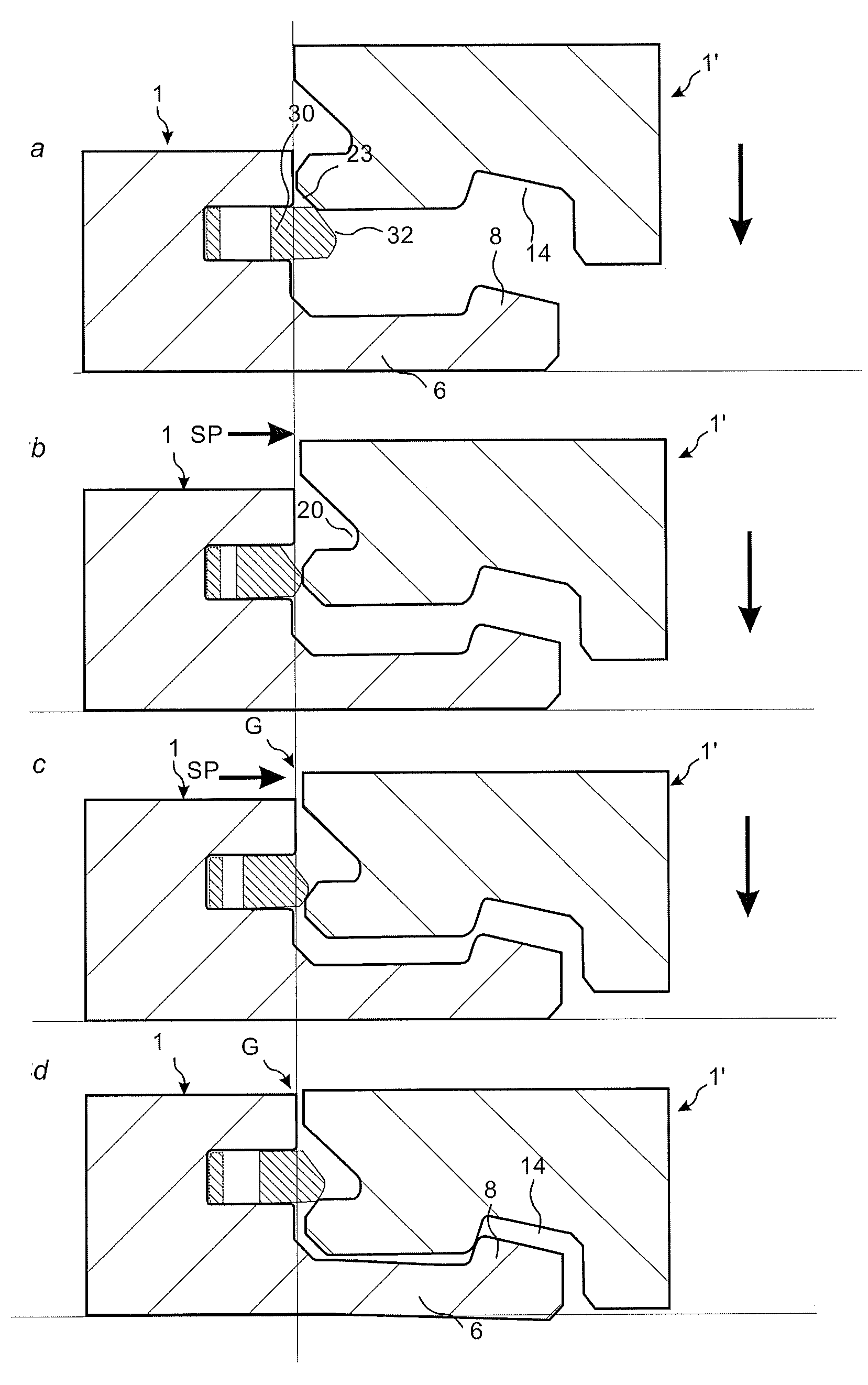
[0089]FIGS. 1-6 and the related description below describe published embodiments and are used to explain the major principles of the invention and to show examples of embodiments that could be used in the invention. The showed embodiments are only examples. It should be emphasized that all types of flexible tongues and one piece tongues which could be used in a locking system allowing vertical folding and / or vertical locking, could be used and applicable part of this description form a part of the present invention.

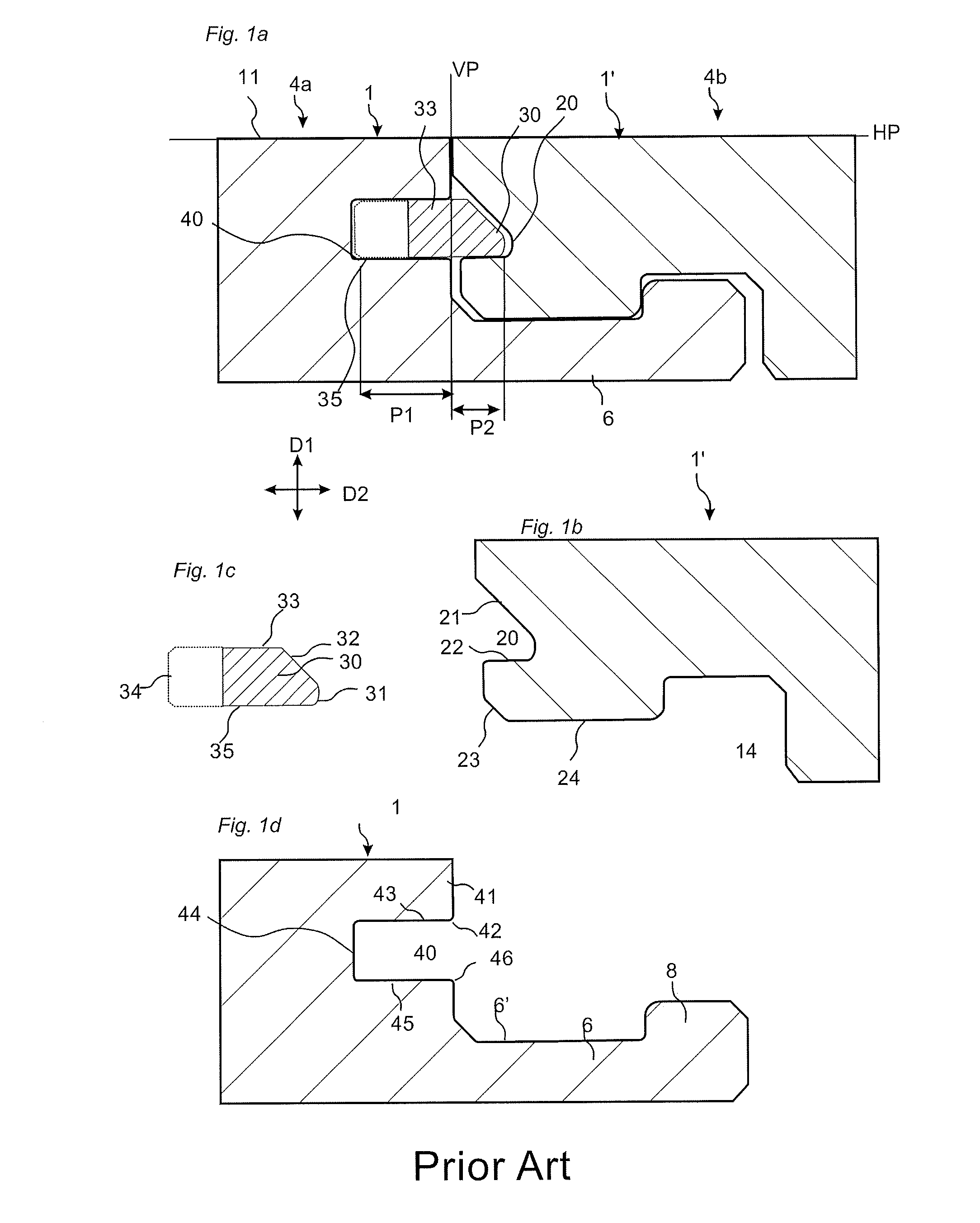
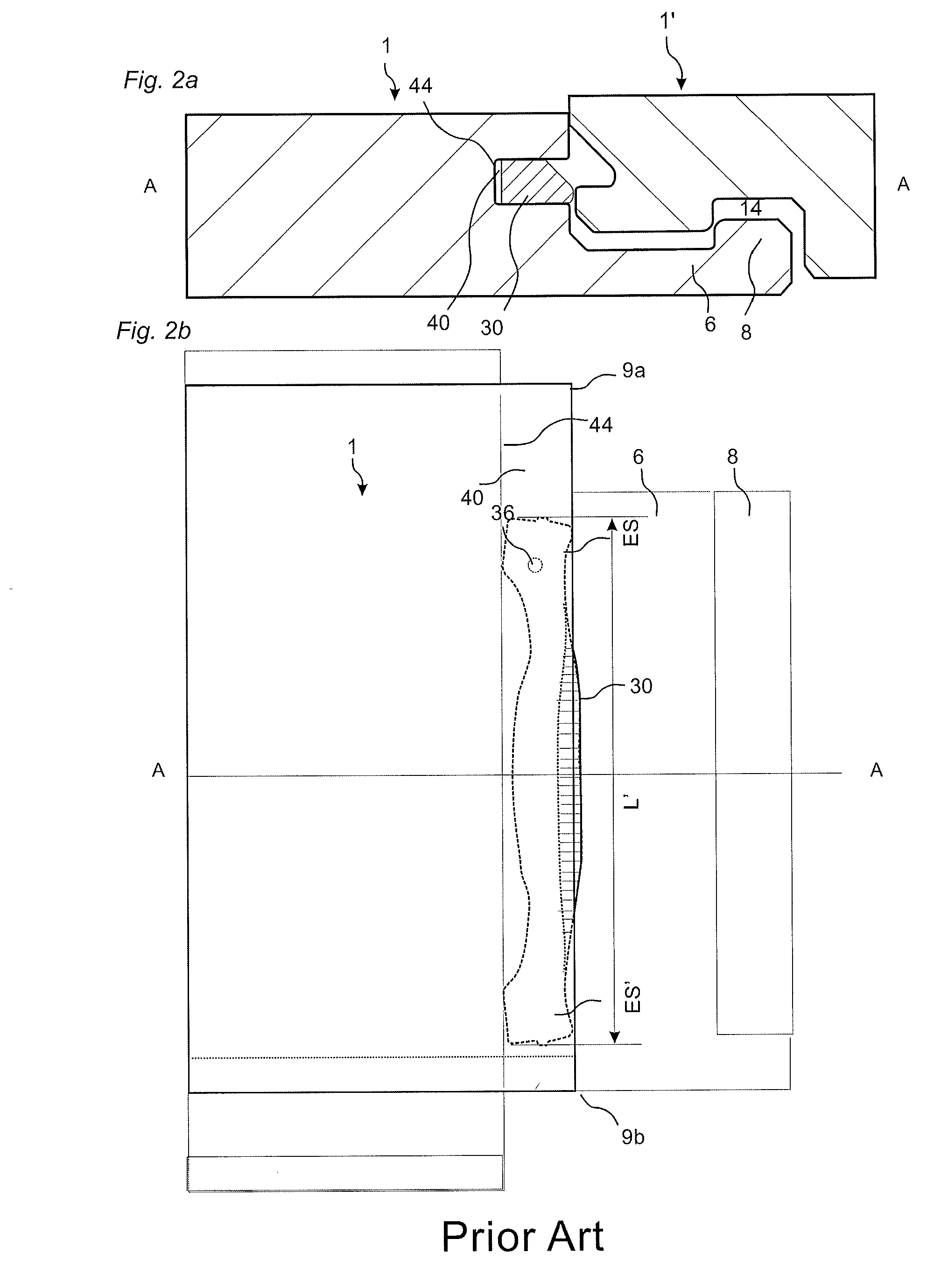
[0090]A prior art floor panel 1, 1′ provided with a mechanical locking system and a displaceable tongue is described with reference to FIGS. 1a-1d.

[0091]FIG. 1a illustrates schematically a cross-section of a joint between a short edge joint edge 4a of a panel 1 and an opposite short edge joint edge 4b of a second panel 1′.

[0092]The front faces of the panels are essentially positioned in a common horizontal plane HP, and the upper parts 21, 41 of the joint edges 4a, 4b ab...


PUM


Abstract

Floor panels (1, 1′, 1″) are shown, which are provided with a mechanical locking system on long and short edges (5a, 5b, 4a, 4b) allowing installation with vertical folding and where the long edge (5a, 5b) locking system prevents separation of the short edges (4a, 4b) during the folding action.

Description

CROSS REFERENCE TO RELATED APPLICATIONS[0001]The present application is a division of U.S. application Ser. No. 11 / 923,836, filed on Oct. 25, 2007, which claims the benefit of U.S. Provisional Application No. 60 / 858,968, filed on Nov. 15, 2006. The entire contents of each of U.S. application Ser. No. 11 / 923,836 and U.S. Provisional Application No. 60 / 858,968 are hereby incorporated herein by reference in their entirety.AREA OF INVENTION[0002]The invention generally relates to the field of floor panels with mechanical locking systems with a flexible and displaceable tongue allowing easy installation. The invention provides new improved locking systems and installation methods.BACKGROUND OF THE INVENTION[0003]In particular, yet not restrictive manner, the invention concerns a mechanical locking system for rectangular floor panels with long and short edges. It should be emphasized that long and short edges are only used to simplify the description. The panels could also be square. Howe...

Claims


Application Information

Patent Timeline
Patent Type & Authority Applications(United States)
IPC IPC(8): E04F15/02
CPCE04F15/02038E04F15/02E04F15/04E04F2201/0138E04F2201/0153E04F2201/0523Y10T428/167Y10T24/45251E04C2/38
Inventor PERVAN, DARKO
Owner VÄLINGE INNOVATION AB
Why Eureka
Try Eureka