
Liquid ejection apparatus, controlling method thereof, and computer-readable medium for liquid ejection

a liquid ejection and control method technology, applied in the direction of printing, other printing apparatus, etc., can solve the problems of reducing the minimum drive voltage, affecting the degree of deterioration of the piezoelectric element, so as to reduce the differences of deterioration among the piezoelectric element units, increase the difference, and reduce the effect of deterioration

Active Publication Date: 2014-03-13
BROTHER KOGYO KK
View PDF2 Cites 1 Cited by
  • Summary
  • Abstract
  • Description
  • Claims
  • Application Information

AI Technical Summary

Benefits of technology

The patent text describes a liquid ejection apparatus and its control method that can reduce breakage of voltage supply circuits and control the deterioration of piezoelectric elements in the apparatus. By reducing the difference in accumulated time between the maximum and minimum times that a piezoelectric element unit is in the driven state, the apparatus can control the deterioration of those elements that are not in use. This results in reduced differences in deterioration between the piezoelectric elements and improved performance and reliability of the liquid ejection apparatus.

Problems solved by technology

However, this may lead to differences between the piezoelectric elements with respect to the degree of deterioration.
This may lead to breakage of a power circuit for supplying the drive voltage.
Accordingly, a heating amount of the linear regulator corresponding to the minimum drive voltage may become relatively large, and the voltage supply circuit may be damaged.

Method used


Image

  • Liquid ejection apparatus, controlling method thereof, and computer-readable medium for liquid ejection
  • Liquid ejection apparatus, controlling method thereof, and computer-readable medium for liquid ejection
  • Liquid ejection apparatus, controlling method thereof, and computer-readable medium for liquid ejection

Examples


Embodiment Construction

[0020]Example embodiments are described in detail herein with reference to the accompanying drawings in which like reference numerals are used for corresponding parts in the various drawings.

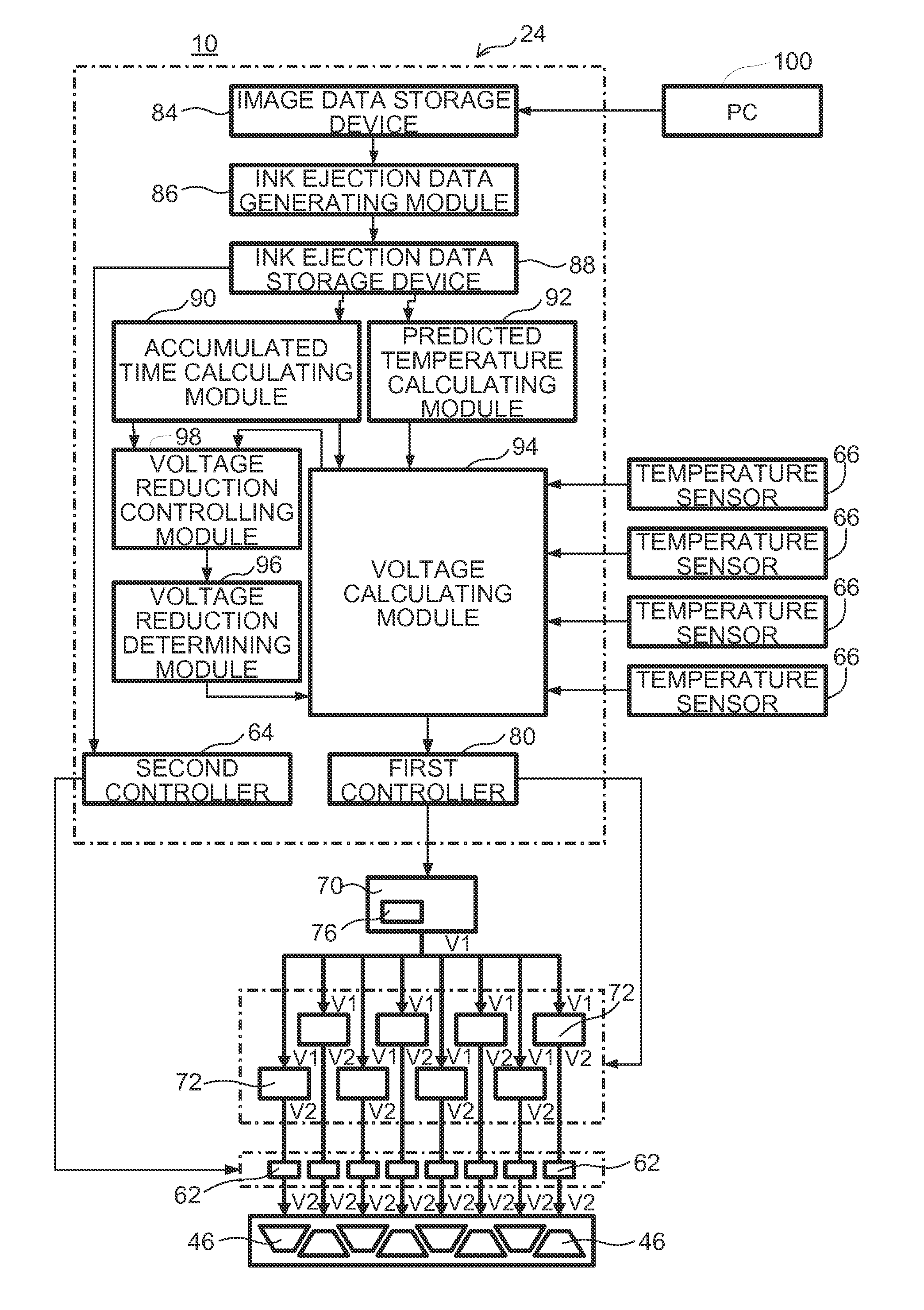
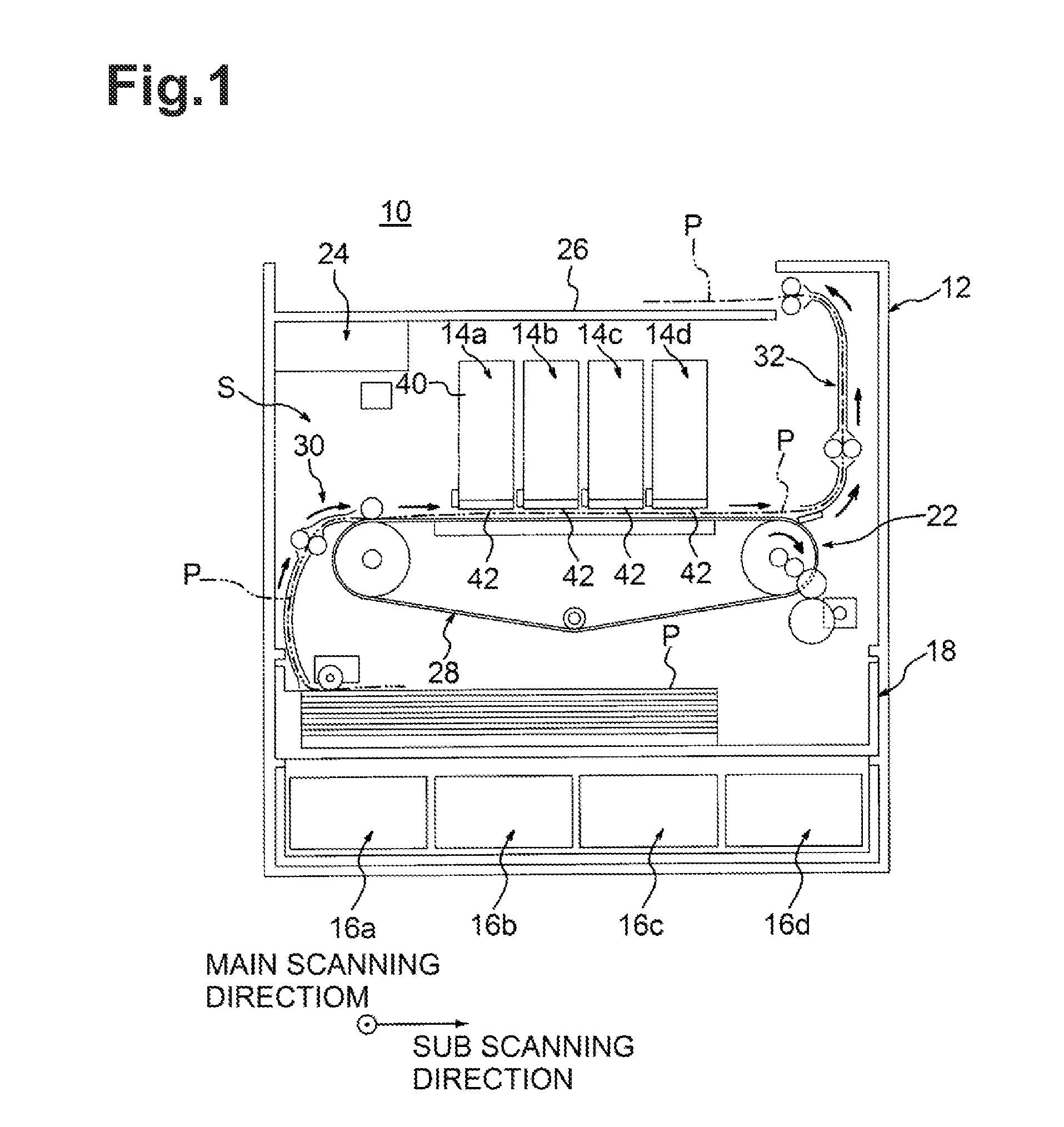
[0021]As depicted in FIG. 1, a liquid ejection apparatus, e.g., an inkjet printer 10, may comprise a case 12, a plurality of, e.g., four, head units 14a-14d, each corresponding to one of a plurality of, e.g., four, colors (black, cyan, magenta, yellow) of liquid, e.g., ink, and ink tanks 16a-16d, each configured to store a different one of the plurality of colors of liquid. The inkjet printer 10 may further comprise a recording medium accommodating portion 18 configured to accommodate recording mediums P (e.g., paper, cloth, film, etc.), a conveying mechanism 22 configured to convey the recording mediums P, and a controlling device 24 configured to perform various controls.

[0022]As depicted in FIG. 1, the interior of the case 12 may have a space S which may store various devices and units. An up...


PUM


Abstract

A liquid ejection apparatus comprises a plurality of piezoelectric element units, which can be driven to eject liquid by changing a drive voltage, and a control device. The control device may calculate an accumulated time for each of the piezoelectric element units. The accumulated times may be a time that a respective piezoelectric element unit is in a driven state. The control device may also identify a first piezoelectric element unit having a maximum accumulated time and a second piezoelectric element unit having a minimum accumulated time from among the piezoelectric element units. The control device may reduce the drive voltage applied to one or more of the piezoelectric element units that are not in the driven state to a lower voltage, when the control device determines that the difference between the maximum accumulated time and the minimum accumulated time is less than a predetermined time.

Description

CROSS-REFERENCE TO RELATED APPLICATION[0001]This application claims priority from Japanese Patent Application No. 2012-081569 filed on Sep. 13, 2012, which is incorporated herein by reference.FIELD OF DISCLOSURE[0002]The disclosure herein relates to a liquid ejection apparatus comprising a plurality of piezoelectric element units configured to eject liquid and a control method of the liquid ejection apparatus, and computer-readable media for controlling liquid ejection.BACKGROUND[0003]A known liquid ejection apparatus, e.g., an inkjet printer, includes an ink ejection head including a plurality of piezoelectric element units. In the inkjet printer, each of the piezoelectric element units of the ink ejection head includes a polarized piezoelectric element. A drive voltage is applied to the piezoelectric elements to drive the piezoelectric elements. Thus, ink is ejected from the ink ejection head onto a recording medium. When the drive voltage is applied to the piezoelectric elements ...

Claims


Application Information

Patent Timeline
Patent Type & Authority Applications(United States)
IPC IPC(8): B41J2/045
CPCB41J2/04581B41J2/0454B41J2/04563B41J2/04588B41J2/0459B41J2/04593
Inventor UCHINO, SHUNJI
Owner BROTHER KOGYO KK
Learn More