Distance measurement apparatus

a technology of distance measurement and measuring device, which is applied in the direction of distance measurement, instruments, surveying and navigation, etc., can solve the problems of complex configuration and control protocol

Active Publication Date: 2014-03-13
RICOH KK
View PDF3 Cites 29 Cited by
  • Summary
  • Abstract
  • Description
  • Claims
  • Application Information

AI Technical Summary

Problems solved by technology

However, the laser radar apparatus of JP-2009-145107-A has a complex configuration and control protocol, and is therefore costly.

Method used


Image

  • Distance measurement apparatus
  • Distance measurement apparatus
  • Distance measurement apparatus

Examples


Embodiment Construction

[0028]A description is now given of exemplary embodiments of the present invention. It should be noted that although such terms as first, second, etc. may be used herein to describe various elements, components, regions, layers and / or sections, it should be understood that such elements, components, regions, layers and / or sections are not limited thereby because such terms are relative, that is, used only to distinguish one element, component, region, layer or section from another region, layer or section. Thus, for example, a first element, component, region, layer or section discussed below could be termed a second element, component, region, layer or section without departing from the teachings of the present invention.

[0029]In addition, it should be noted that the terminology used herein is for the purpose of describing particular embodiments only and is not intended to be limiting of the present invention. Thus, for example, as used herein, the singular forms “a”, “an” and “the...


PUM


Abstract

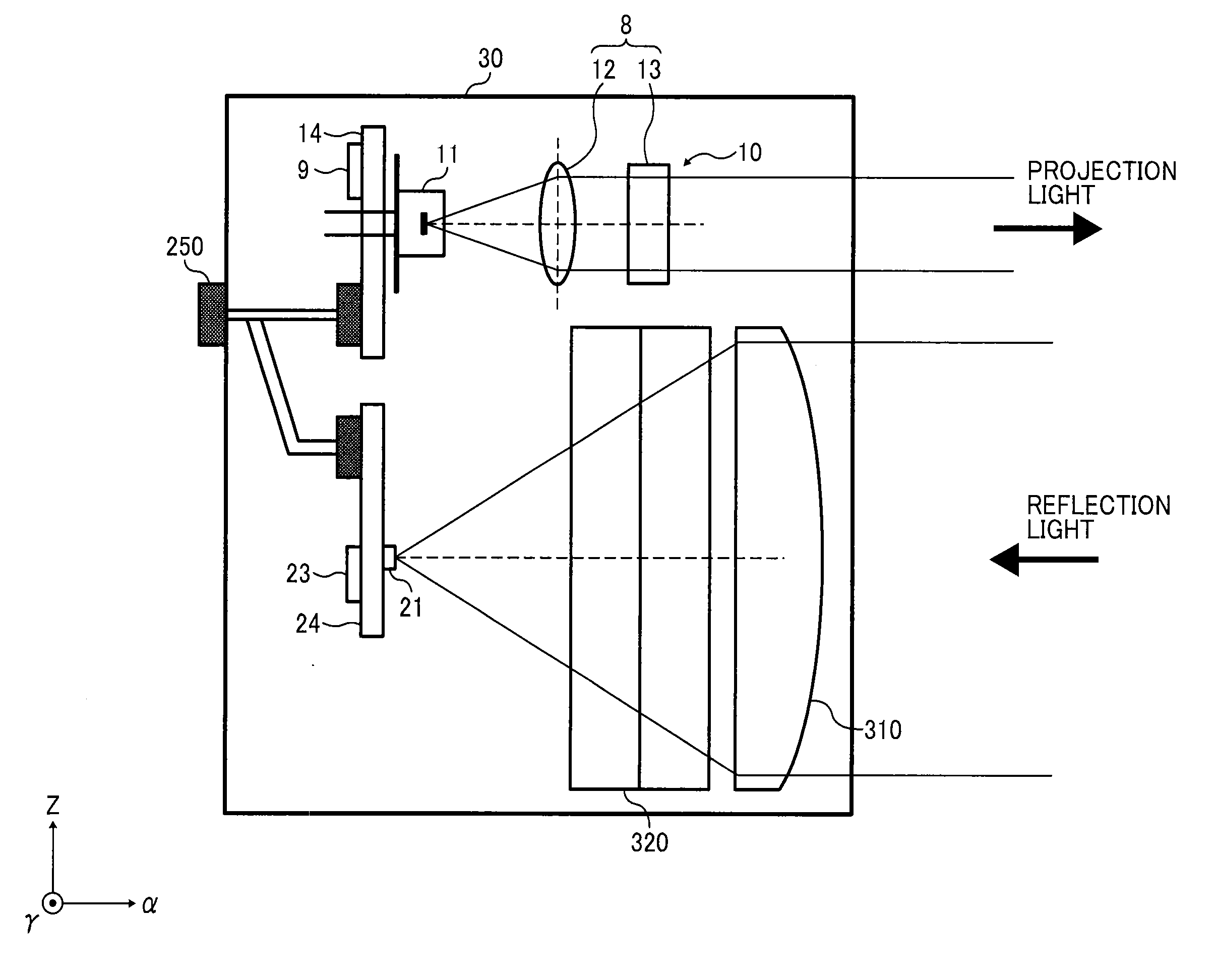
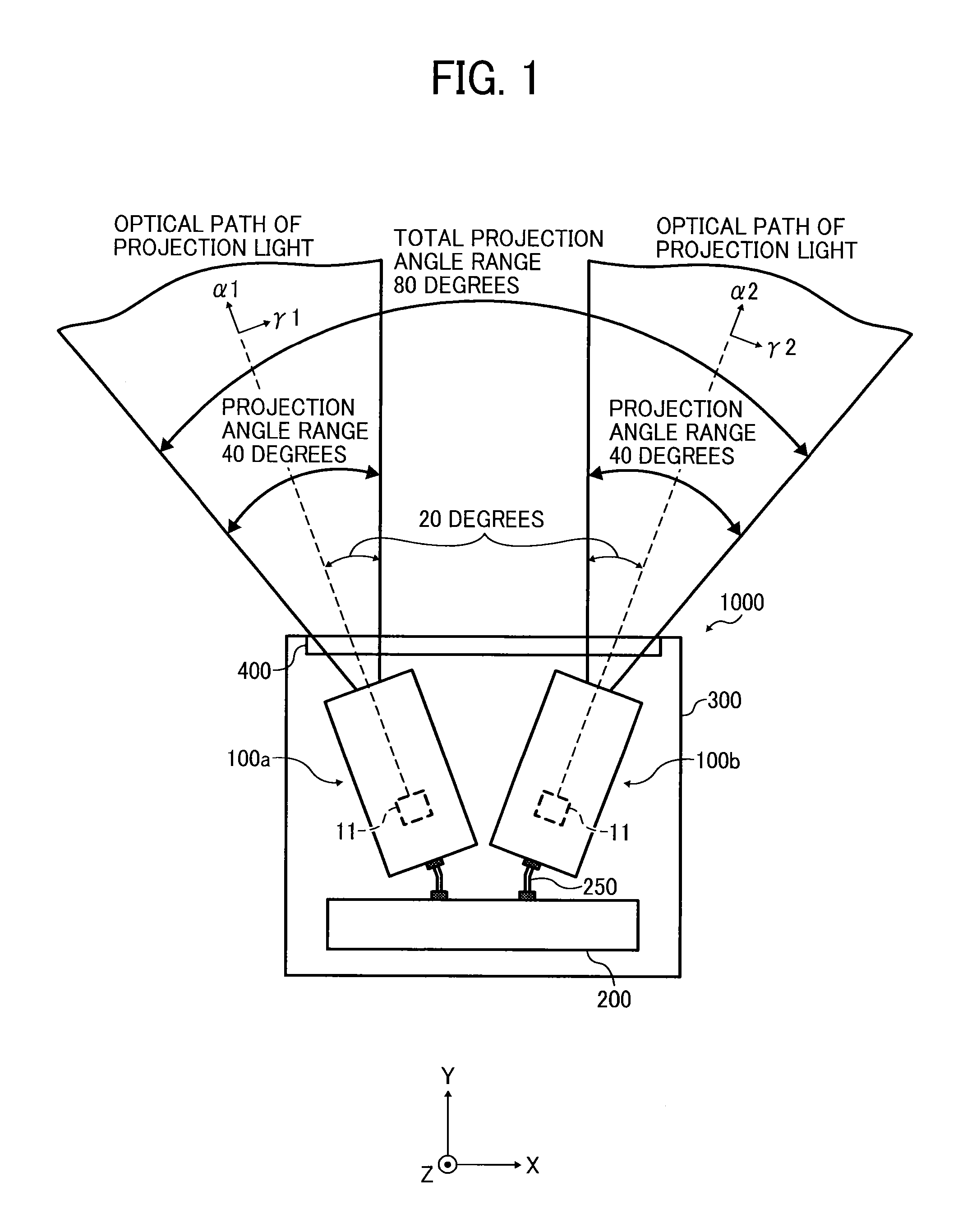
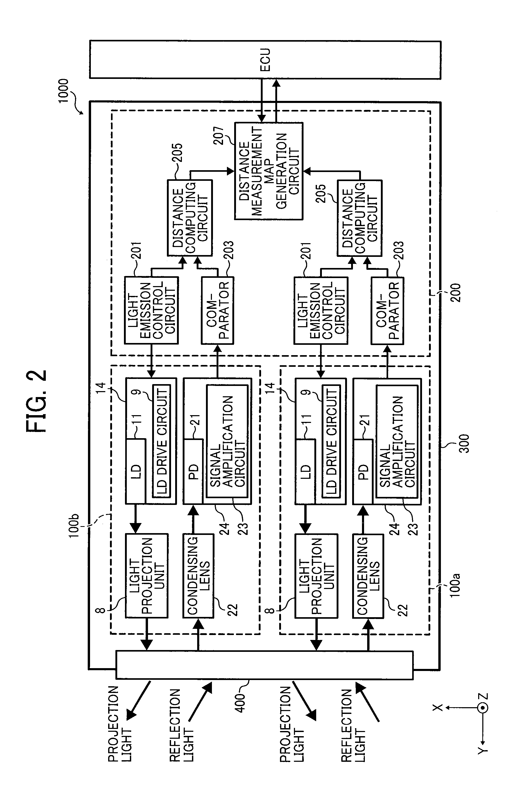
A distance measurement apparatus that measures distance to a target by irradiating the target with laser beams and detecting light reflected by the target includes a light projection unit. The distance measurement apparatus also includes a plurality of light emission units to emit a plurality of laser beams onto the target while setting optical paths of the plurality of laser beams radially along a given virtual plane; and a light receiving unit including a plurality of light receivers to receive the plurality of laser beams projected from the light projection unit and reflected by the target.

Description

CROSS-REFERENCE TO RELATED APPLICATION[0001]This application claims priority pursuant to 35 U.S.C. §119 to Japanese Patent Application No. 2012-201054, filed on Sep. 13, 2012 in the Japan Patent Office, the disclosure of which is incorporated by reference herein in its entirety.BACKGROUND[0002]1. Technical Field[0003]The present invention generally relates to a distance measurement apparatus, and more particularly to a distance measurement apparatus that irradiates a target with light, receives reflection light to measure a distance to the target.[0004]2. Background Art[0005]In conventional laser radar apparatuses such as that disclosed in JP-2009-145107-A, light emitted from a laser diode is radiated to a given area of an target via an oscillation mirror, which can oscillate about a first axis and a second axis perpendicular to the first axis, and a mirror unit having a plurality of mirrors having different inclination angles with respect to a third axis perpendicular to the first ...

Claims


Application Information

Patent Timeline
Patent Type & Authority Applications(United States)
IPC IPC(8): G01C3/08G01S7/4863G01S17/00
CPCG01C3/08G01S7/484G01S7/4863G01S17/10G01S17/00
Inventor SUZUKI, SHUICHIYOSHIMURA, KENICHINAKAJIMA, MITSURUHAYASHI, YUSUKE
Owner RICOH KK
Why Eureka
Try Eureka