Method and device for driving LED element, illumination apparatus, and display apparatus

a technology of led elements and illumination apparatus, applied in static indicating devices, instruments, printing, etc., can solve the problems of difficult to obtain a color low in chroma, heavy environmental load, inferior point of light emission efficiency of the latter illumination apparatus, etc., and achieve the effect of driving

Inactive Publication Date: 2005-08-04
SHARP KK
View PDF2 Cites 264 Cited by
  • Summary
  • Abstract
  • Description
  • Claims
  • Application Information

AI Technical Summary

Benefits of technology

[0009] An object of the present invention is to provide a driving method and a driving device for effectively driving an LED

Problems solved by technology

However, because ordinary LED elements are high in purity of color of emitted light, it is difficult to obtain a color low in chroma, suitable for an illumination apparatus, such as white, only by an LED element having therein a layer or layers for emitting light of a single color.
In case of the former illumination apparatus, however, because the LED element for emitting red light is made of a GaAs-base comp

Method used


Image

  • Method and device for driving LED element, illumination apparatus, and display apparatus
  • Method and device for driving LED element, illumination apparatus, and display apparatus
  • Method and device for driving LED element, illumination apparatus, and display apparatus

Examples


embodiment 1

[0031] Hereinafter, Embodiment 1 of the present invention will be described with reference to drawings.

[0032] (Outline of Illumination Apparatus)

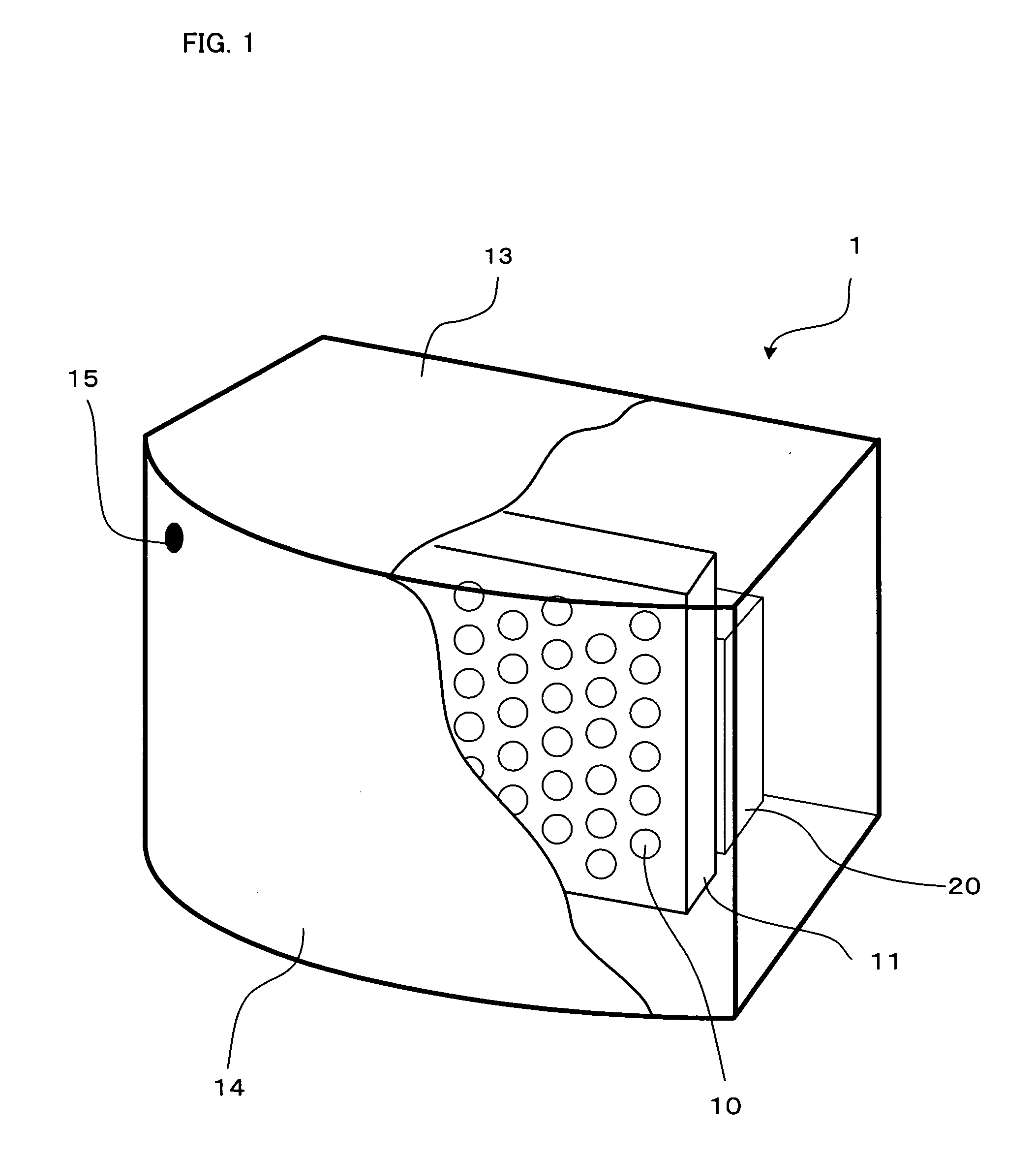
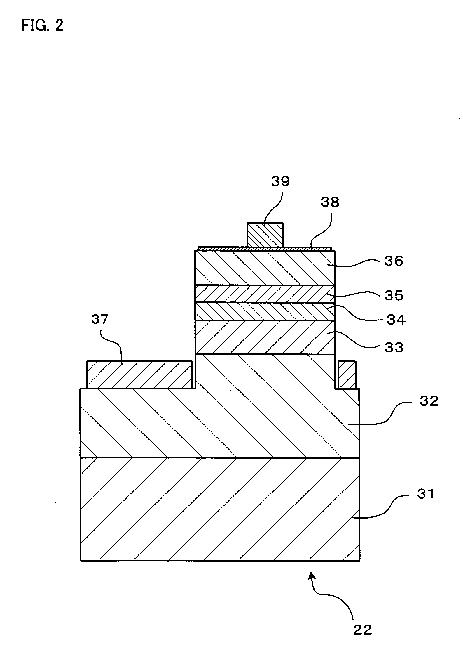
[0033]FIG. 1 shows an external view of an illumination apparatus according to Embodiment 1 of the present invention. The illumination apparatus 1 of FIG. 1 includes therein a large number of LED lamps 10, for example, about sixty LED lamps 10. The LED lamps 10 are arranged in a matrix in a plane to form a panel 11. Each LED lamp 10 includes therein one LED element 22 as shown in FIG. 2. As will be described later, the LED element 22 includes therein two light emitting layers 42 and 44, as shown in FIG. 3, made of nitride-base semiconductor, different from each other in light emission wavelength peak. An LED lighting circuit 20 as a driving device for driving the LED lamps 10 is disposed in the rear of the panel 11. The panel 11 and the LED lighting circuit 20 are accommodated in an outer casing 13. A diffuser 14 is attached to the front f...

embodiment 2

[0074] Next, an illumination apparatus according to Embodiment 2 of the present invention will be described. Because the illumination apparatus of this embodiment is similar to the illumination apparatus of Embodiment 1, only difference from the Embodiment 1 will be mainly described here. In this embodiment, the same components as in the Embodiment 1 are denoted by the same reference numerals as in the Embodiment 1, respectively, to omit the description thereof.

[0075]FIG. 8 shows a block diagram of a control system of the illumination apparatus according to this embodiment. For simplifying the drawing, FIG. 8 shows only one of a large number of LED lamps 10. An LED lighting circuit 60 of FIG. 8, corresponding to the LED lighting circuit 20 of Embodiment 1, includes therein a pulse current value calculator 62, a duty calculator 25, and a pulse current generator 26. A detector 61 is disposed near the LED lamp 10 for receiving a light from the LED lamp 10 and generating an output colo...

embodiment 3

[0077] Next, an illumination apparatus according to Embodiment 3 of the present invention will be described. Because the illumination apparatus of this embodiment is similar to the illumination apparatus of Embodiment 1, only difference from the Embodiment 1 will be mainly described here. In this embodiment, the same components as in the Embodiment 1 are denoted by the same reference numerals as in the Embodiment 1, respectively, to omit the description thereof.

[0078]FIG. 9 shows a block diagram of a control system of the illumination apparatus according to this embodiment. For simplifying the drawing, FIG. 9 shows only three of a large number of LED lamps 10. An LED lighting circuit 70 of FIG. 9, corresponding to the LED lighting circuit 20 of Embodiment 1, includes therein a pulse current value calculator 24, a pulse generation controller 71, and pulse current generators in the same number as LED lamps 10, though FIG. 9 shows only three pulse current generators 72a, 72b, and 72c ...


PUM


Abstract

A driving method and a driving device are provided for an LED element in which light emitting layers different from each other in light emission wavelength peak, put on each other with a barrier layer being interposed, are sandwiched by a pair of p-type and n-type layers, and color of emitted light from which substantially depends only upon driving current value. The method comprises a driving current value calculation step of obtaining a value for designating a current value corresponding to a desired color of emitted light from the LED element; a driving current generation step of generating a driving current having the current value designated by the value obtained in the driving current value calculation step; and a driving current supply step of supplying the LED element with the driving current generated in the driving current generation step.

Description

BACKGROUND OF THE INVENTION [0001] 1. Field of the Invention [0002] The present invention relates to a driving method and a driving device for driving an LED element having therein a plurality of light emitting layers different from each other in light emission wavelength peak, and also to an illumination apparatus and a display apparatus. [0003] 2. Description of the Related Art [0004] As techniques on III-V compound semiconductors and organic compound semiconductors progress, illumination apparatus have been proposed that use light emitting diodes (LEDs) made of those materials. However, because ordinary LED elements are high in purity of color of emitted light, it is difficult to obtain a color low in chroma, suitable for an illumination apparatus, such as white, only by an LED element having therein a layer or layers for emitting light of a single color. For this reason, an illumination apparatus has been devised that uses LED lamps in each of which three kinds of LED elements f...

Claims


Application Information

Patent Timeline
IPC IPC(8): B41J2/435B41J2/47H05B37/02H01L33/06H01L33/32
CPCH05B33/0803H05B33/0818H05B33/0869H05B33/0863H05B33/086H05B45/22H05B45/20H05B45/32
Inventor KAWAGUCHI, YOSHINOBUITO, SHIGETOSHI
Owner SHARP KK
Why Eureka
Try Eureka