Cleaning pad with visually discernible indicator, steam mop and method

a technology of visually discernible indicators and cleaning pads, which is applied in the direction of vacuum cleaners, carpet cleaners, cleaning processes and apparatuses, etc., can solve the problems of cumbersome and user-dependent operation, affecting the cleaning effect, and reducing the cleaning performance of the cleaning pads

Active Publication Date: 2014-03-20
BISSELL INC
View PDF14 Cites 8 Cited by
  • Summary
  • Abstract
  • Description
  • Claims
  • Application Information

AI Technical Summary

Problems solved by technology

During use, as the cleaning pad attracts and absorbs larger amounts of soil over time, the cleaning effectiveness can diminish.
Additionally, cleaning performance of the pad can also diminish when auxiliary compositions in...

Method used


Image

  • Cleaning pad with visually discernible indicator, steam mop and method
  • Cleaning pad with visually discernible indicator, steam mop and method
  • Cleaning pad with visually discernible indicator, steam mop and method

Examples


Embodiment Construction

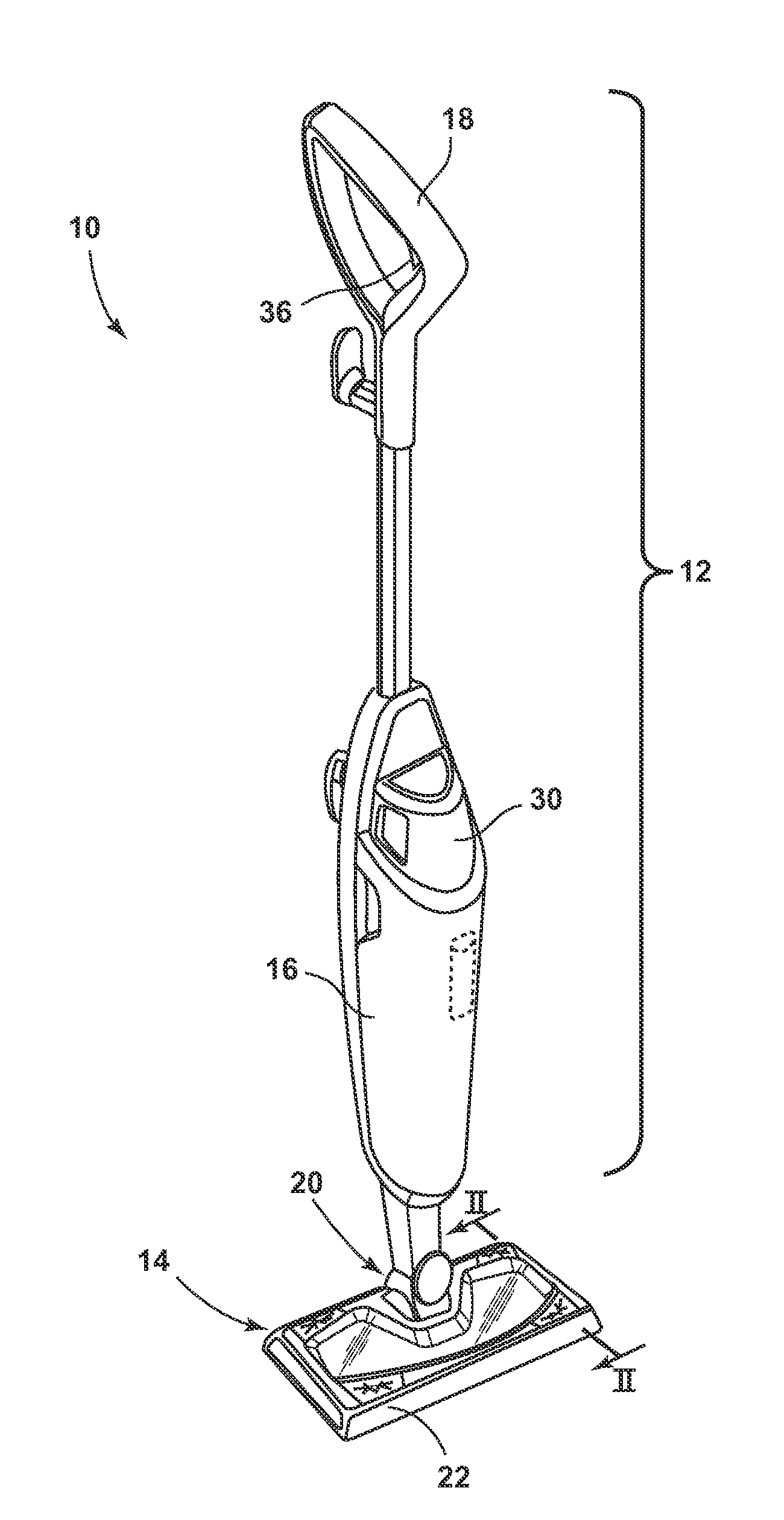
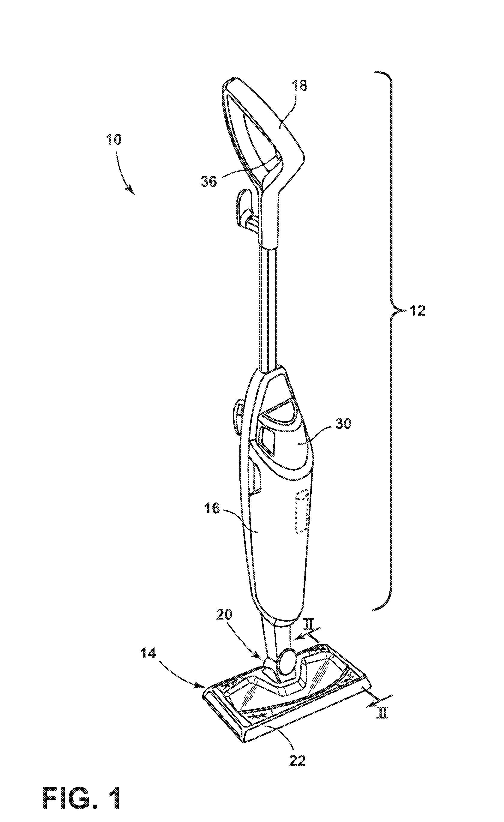
[0013]The invention generally relates to a surface cleaning apparatus with heat and a cleaning composition delivery. Referring to FIG. 1, a steam mop 10 according to one aspect of the invention comprises an upright handle assembly 12 mounted to a cleaning foot assembly 14. The upright handle assembly 12 further comprises a handle housing 16 located between a handle grip 18 and a joint 20. The cleaning foot assembly 14 is attached to the joint 20 to moveably mount the foot assembly 14 to the handle assembly 12. In one embodiment, the joint 20 can comprise a universal joint 20, such that the foot assembly 14 can pivot about at least two axes relative to the handle housing 16.

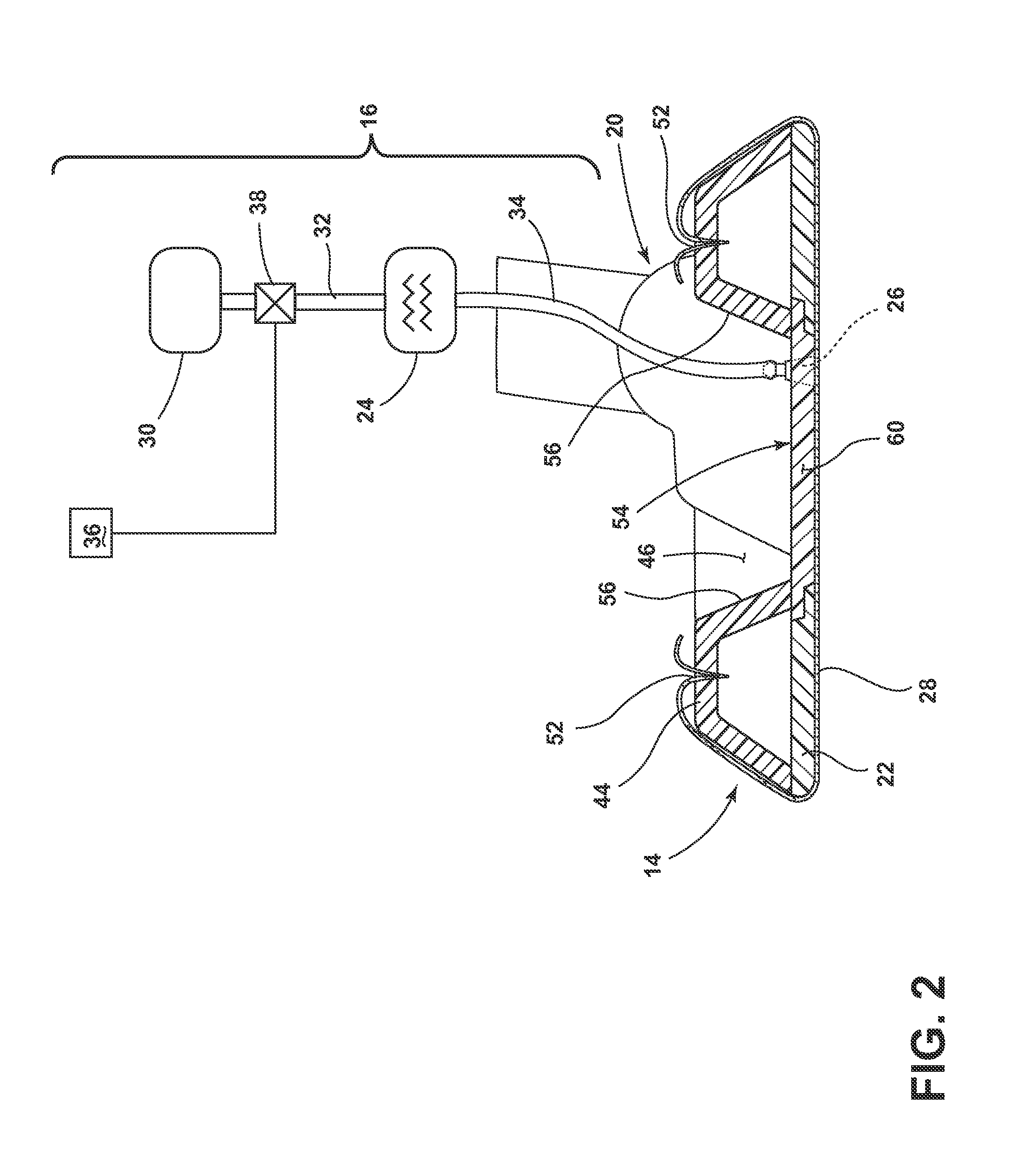
[0014]With reference to FIG. 2, the foot assembly 14 further comprises a steam frame 22 and a cleaning pad 28 removably attached to a lower surface of the steam frame 22. The steam frame 22 comprises a generally rectangular housing having at least one steam outlet 26 formed therethrough for delivering steam to the...


PUM


Abstract

A cleaning pad for use with a surface cleaning appliance, such as a steam mop, includes a cleaning composition and at least one visually discernible indicator that alerts a user to the condition of the cleaning pad. The visually discernible indicator can change color as the cleaning composition is consumed.

Description

CROSS-REFERENCE TO RELATED APPLICATION[0001]This application claims the benefit of U.S. Provisional Patent Application No. 61 / 701,934, filed Sep. 17, 2012, which is incorporated herein by reference in its entirety.BACKGROUND OF THE INVENTION[0002]Devices such as steam mops and handheld steamers are configured for cleaning a wide variety of common household surfaces such as bare flooring, including tile, hardwood, laminate, vinyl, and linoleum, as well as countertops, stove tops and the like. Typically, steam mops comprise at least one tank or reservoir for storing liquid that is fluidly connected to a selectively engageable pump or valve. The outlet of the pump or valve is fluidly connected to a steam generator, which comprises a heating element for heating the liquid. The steam generator produces steam, which can be directed towards the surface to be cleaned through a distributor nozzle or a manifold located in a foot or cleaning head that engages the surface to be cleaned. Steam i...

Claims


Application Information

Patent Timeline
IPC IPC(8): A47L13/22A47L13/17
CPCA47L13/17A47L13/225
Inventor HANSEN, ERIC J.
Owner BISSELL INC
Why Eureka
Try Eureka