Steam mop

A steam and mop technology, applied in the field of steam mops, can solve problems such as the danger of dry burning, limit the scope of application, etc., and achieve the effects of preventing dry burning, effective cleaning, and easy handling and storage.

Active Publication Date: 2013-05-01
SUZHOU DELAI ELECTRICAL APPLIANCE
View PDF6 Cites 8 Cited by
  • Summary
  • Abstract
  • Description
  • Claims
  • Application Information

AI Technical Summary

Problems solved by technology

[0002] The main structure of the steam mop is the handle, the body and the steam floor brush. Generally, a water tank is installed in the body, and a steam generator is installed in the body or the steam floor brush, and the water outlet of the water tank is located at the lower part. The water can cover the water outlet to ensure that it can normally supply water to the steam generator, such as a steam mop disclosed in Chinese patent CN201208239Y, the water tank is arranged on the mop rod, the steam generator is arranged in the mop head, the water tank and the mop The heads are connected by a piston pump. When the steam mop is tilted until the water in the water tank cannot submerge the water outlet connected to the piston pump, it cannot supply water to the steam generator, causing the danger of dry burning. In summary, such steam The mop can only be used with the steam brush head tilted down relatively, which limits its scope of application

Method used


Image

  • Steam mop
  • Steam mop
  • Steam mop

Examples


Embodiment Construction

[0018] Below in conjunction with the embodiment shown in the accompanying drawings, the present invention is described in detail as follows:

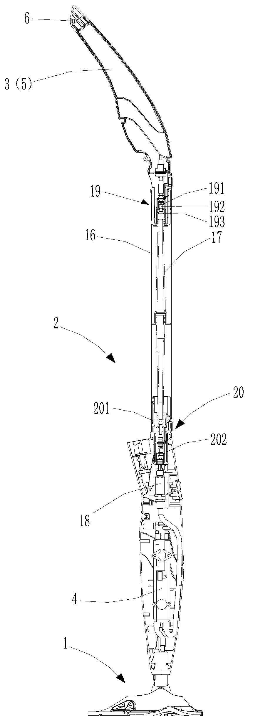
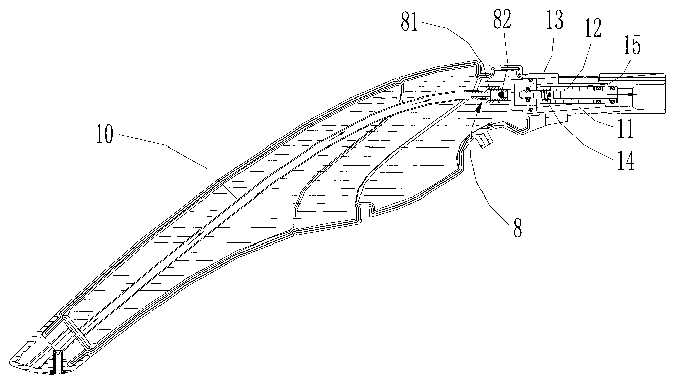
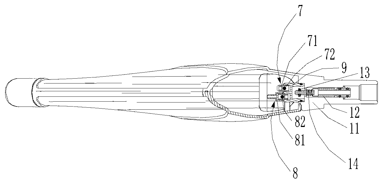
[0019] as attached figure 1 to attach image 3As shown, the steam mop of the present invention includes a steam brush head 1 at the bottom, a body 2 that can be turned over in multiple directions on the upper part of the steam brush head 1, and a steam supply mechanism for providing steam to the steam brush head 1. Among the examples, the steam supply mechanism is arranged in the fuselage 2, the steam supply mechanism includes a water tank 3 and a steam generator 4 communicated with the water tank 3, the water tank 3 is located at the upper end of the fuselage 2, and the water tank 3 constitutes the steam mop for the user. Hold the handle 5 for operation, specifically, the lower end of the water tank 3 is provided with a control valve assembly and a water outlet valve, and the upper end is provided with a one-way inlet valve 6, and the...


PUM


Abstract

The invention discloses a steam mop which comprises a steam brush head at the lower part, and a machine body arranged on the upper part of the steam brush head in a manner of overturning in multiple directions, wherein the machine body is internally provided with a steam supply mechanism used for providing stream for the steam brush head; the steam supply mechanism comprises a water tank and a steam generator communicated with the water tank; the water tank is position at the upper end of the machine body; the water tank is provided with a handle, held by a user, of the steam mop; the water tank is provided with a control valve component capable of forming passages in the positive and negative directions; the water tank is arranged at the upmost end of the whole steam mop and is taken as the handle operated by the user, so that the whole mop is smaller in size and convenient in transportation and storage; and when the mop works at any inclination angle, water in the water tank can be prevented from entering the steam generator on the premise that water exists in the water tank, a dry burning phenomenon can be prevented, efficient and effective cleaning work can be ensured, and the steam mop is suitable for being popularized and used in household stream mops.

Description

technical field [0001] The invention relates to a steam cleaning device, in particular to a steam mop. Background technique [0002] The main structure of the steam mop is the handle, the body and the steam floor brush. Generally, a water tank is installed in the body, and a steam generator is installed in the body or the steam floor brush, and the water outlet of the water tank is located at the lower part. The water can cover the water outlet to ensure that it can normally supply water to the steam generator, such as a steam mop disclosed in Chinese patent CN201208239Y, the water tank is arranged on the mop rod, the steam generator is arranged in the mop head, the water tank and the mop The heads are connected by a piston pump. When the steam mop is tilted until the water in the water tank cannot submerge the water outlet connected to the piston pump, it cannot supply water to the steam generator, causing the danger of dry burning. In summary, such steam The mop can only ...

Claims


Application Information

Patent Timeline
Patent Type & Authority Applications(China)
IPC IPC(8): A47L11/34A47L11/40
Inventor 卞庄
Owner SUZHOU DELAI ELECTRICAL APPLIANCE
Why Eureka
Try Eureka