Spall-Resistant Cementitious Material

a cementitious material and brittle technology, applied in the field of cementitious materials, can solve the problems of compressive strength, dsp, based cementitious materials are distinctly brittle,

Inactive Publication Date: 2014-03-20
BRIEN JOSHUA V
View PDF1 Cites 15 Cited by
  • Summary
  • Abstract
  • Description
  • Claims
  • Application Information

AI Technical Summary

Benefits of technology

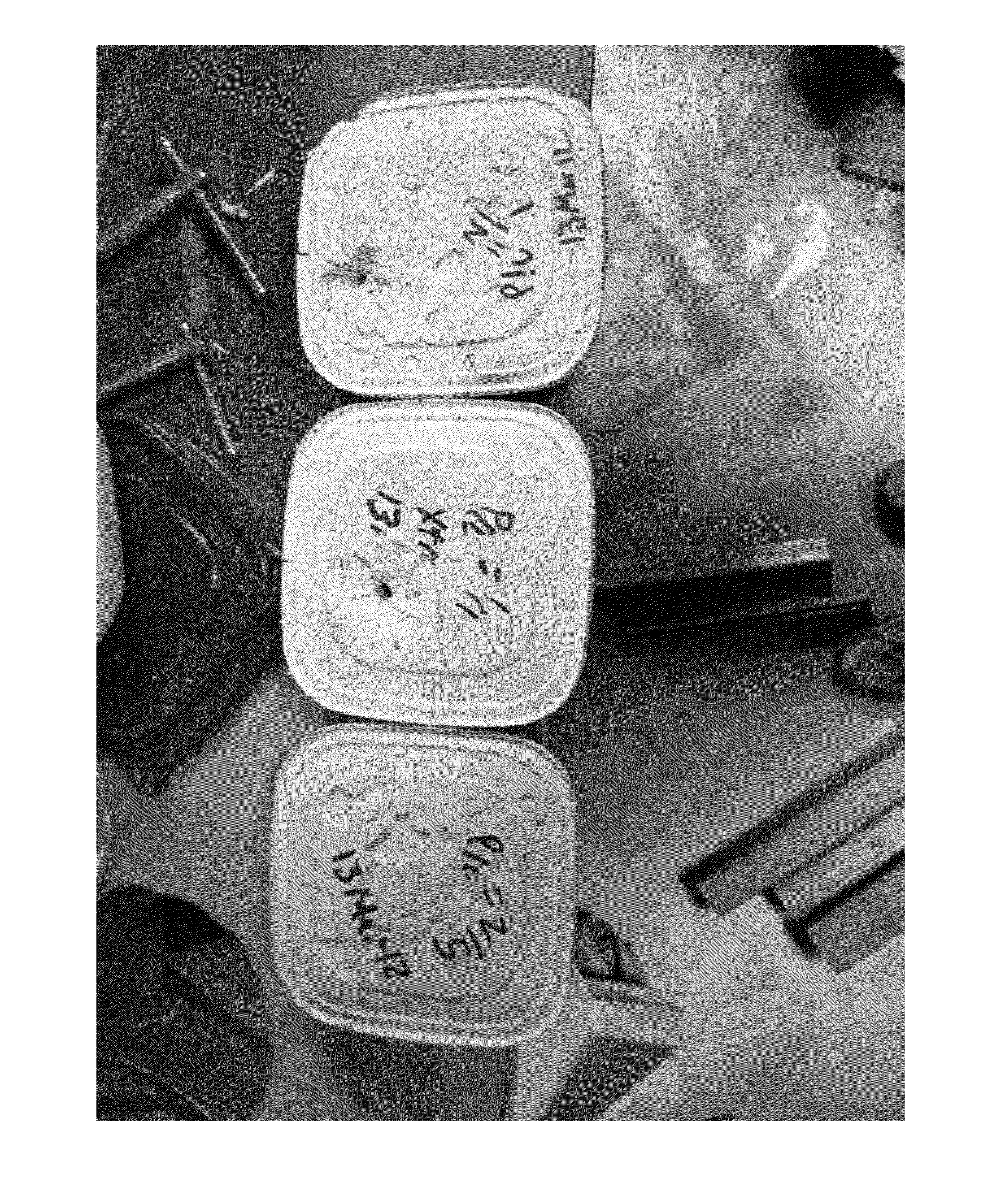
[0028]FIG. 6 shows bullet exits for polymer modified hydraulic cement mortars at polymer cement ratios of 2 / 5 (bottom), 1 / 1 (middle) and 2 / 1 (top) where it can be seen that p / c=2 / 5 stopped the bullet while maintaining structural integrity, p / c=1 / 1 had little spall while maintaining structural integrity and p / c=2 / 1 had even less spall while maintaining structural integrity.
[0029]FIG. 7 shows a bar graph depicting direct tensile strength of polymer modified mortar samples at polymer / cement ratios of 0.15, 0.3 and 0.45.
[0030]FIG. 8 shows a bar graph depicting percent elongation at break for direct tensile strength dog bone samples at polymer / cement ratios of 0.15, 0.3 and 0.45.
[0031]FIG. 9 shows a bar graph depicting flexural strength of polymer modified cement mortar samples at polymer / cement ratios of 0.15, 0.3 and 0.45.
[0032]FIG. 10 shows a bar graph depicting compressive strength of polymer modified cement mortar at polymer / cement ratios of 0.15, 0.3 and 0.45.
[0033]FIG. 11 shows examples of sample specimens for ASTM C307 uni-axial direct tensile strength testing.

Problems solved by technology

The densified spacing packing “DSP” based cementitious materials are however distinctly brittle, the more so the higher the compressive strength.
In fact, although the tensile strength is about one tenth of the compressive strength, the material is intrinsically brittle.
Such behavior of polymeric material has the potential to lead to creep type behavior for select mix designs.
High polymer / cement ratio materials often display a longer plateau for the yield curve as the material fails and the platens of the testing machine move a greater distance during failure when compared with materials more brittle in nature.

Method used


Image

  • Spall-Resistant Cementitious Material
  • Spall-Resistant Cementitious Material
  • Spall-Resistant Cementitious Material

Examples


Embodiment Construction

[0039]The invention now will be described more fully hereinafter. The invention may, however, be embodied in many different forms and should not be construed as limited to the embodiments set forth herein; rather, these embodiments are provided so that this disclosure will be thorough and complete, and will fully convey the scope of the invention to those skilled in the art. As used in this specification and the claims, the singular forms “a,”“an,” and “the” include plural referents unless the context clearly dictates otherwise. “Or” as in “A or B” is conjunctive, not disjunctive, and accordingly in this instance means at least one member of the set {A, B}.

[0040]A material such as is described herein provides inter alia an optionally load-bearing essentially shaped cementitious product manufactured by steps comprising:

[0041](a) admixing a liquid medium, a hydraulic binding agent, a latex polymer and optionally one or more other components, wherein the mass ratio of hydraulic binding...


PUM

PropertyMeasurementUnit
thicknessaaaaaaaaaa
thicknessaaaaaaaaaa
temperatureaaaaaaaaaa

Abstract

Disclosed is an essentially shaped cementitious product wherein the direct tensile strength of the product as determined by ASTM C307 is at least 120% of a predicted direct tensile strength of the product per an equation selected from the group consisting of f′dt=0.06*f′c, f′dt=0.07*f′c, f′dt=0.08*f′c and f′dt=0.11*f′c, and wherein the flexural strength of the product as determined by ASTM C348 is at least 150% of a predicted flexural strength of the product per an equation selected from the group consisting of f′r=0.1*f′c, f′r=0.17*f′c, f′r=9.5*((f′c)̂0.5) and f′r=7.5*((f′c)̂0.5).

Description

CROSS-REFERENCE TO RELATED APPLICATIONS[0001]This application claims priority to and benefit under 35 U.S.C. §119(e) to U.S. Provisional Patent Application Ser. No. 61 / 702,404, filed on Sep. 18, 2012, in the name of the present inventor, this provisional application being incorporated herein by reference.FIELD OF THE INVENTION[0002]The field relates to a cementitious material that possesses favorable toughness and resists spalling.BACKGROUND OF THE INVENTION[0003]There is a long-felt need for a cementitious material having sufficient strength while also possessing favorable toughness. Typically, overall strength decreases, with one example being compressive strength, while toughness increases. Strength is defined as force per unit area, i.e. energy per unit volume, while toughness is energy per unit area.[0004]The toughness index, as evaluated by the area under the load-deflection curve, is considered as a measure of the energy absorption capability of the material during fracture i...

Claims


Application Information

Patent Timeline
Patent Type & Authority Applications(United States)
IPC IPC(8): C04B24/24
CPCC04B24/24C04B28/02C04B2111/00974Y02W30/91C04B14/06C04B14/28C04B16/06C04B24/26C04B2103/12C04B2103/22C04B2103/32C04B2103/40C04B2103/44C04B2103/50C04B14/106C04B18/146C04B22/10C04B24/06C04B24/16C04B24/18C04B24/383C04B2103/0066C04B26/045F41H5/023
Inventor BRIEN, JOSHUA V.
Owner BRIEN JOSHUA V
Why Eureka
Try Eureka