Systems and methods for using radar-adaptive beam pattern for wingtip protection

a technology of radar adaptive beam and protection wingtip, which is applied in the direction of aircraft braking arrangement, navigation instruments, instruments, etc., can solve the problems of insufficient time for aircrew to respond to the given situation, the safety problem of aircraft wingtips clipping obstacles, and the cost of solutions. limited

Inactive Publication Date: 2014-03-27
HONEYWELL INT INC
View PDF22 Cites 12 Cited by
  • Summary
  • Abstract
  • Description
  • Claims
  • Application Information

AI Technical Summary

Problems solved by technology

Currently there exists an expensive safety problem of aircraft wingtips clipping obstacles (e.g., 2011 Paris Air Show, an A380 accident in which a wing hit a building; 2012 Chicago O'Hare accident in which a Boeing 747 cargo aircraft's wing clipped an Embraer 140's rudder; 2011 Boston Logan Int.
A challenging drawback of this solution is the fact that the sensor signal covers only the directly forward area in front of the wingtip and leaving the side wingtip angles uncovered by the radar signal, which can be dangerous, especially in turns.
Current solutions provide only limited benefit in such cases, as the obstacle would appear in the sensor's field of view (FOV) just before striking the obstacle and, thus, not providing the aircrew sufficient time for suitable reaction with respect to the given situation.

Method used


Image

  • Systems and methods for using radar-adaptive beam pattern for wingtip protection
  • Systems and methods for using radar-adaptive beam pattern for wingtip protection
  • Systems and methods for using radar-adaptive beam pattern for wingtip protection

Examples


Embodiment Construction

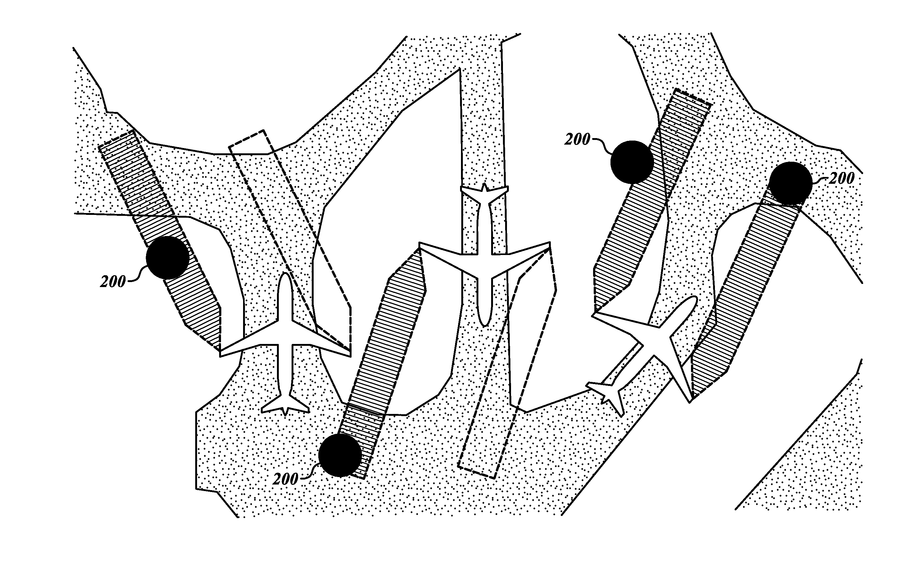
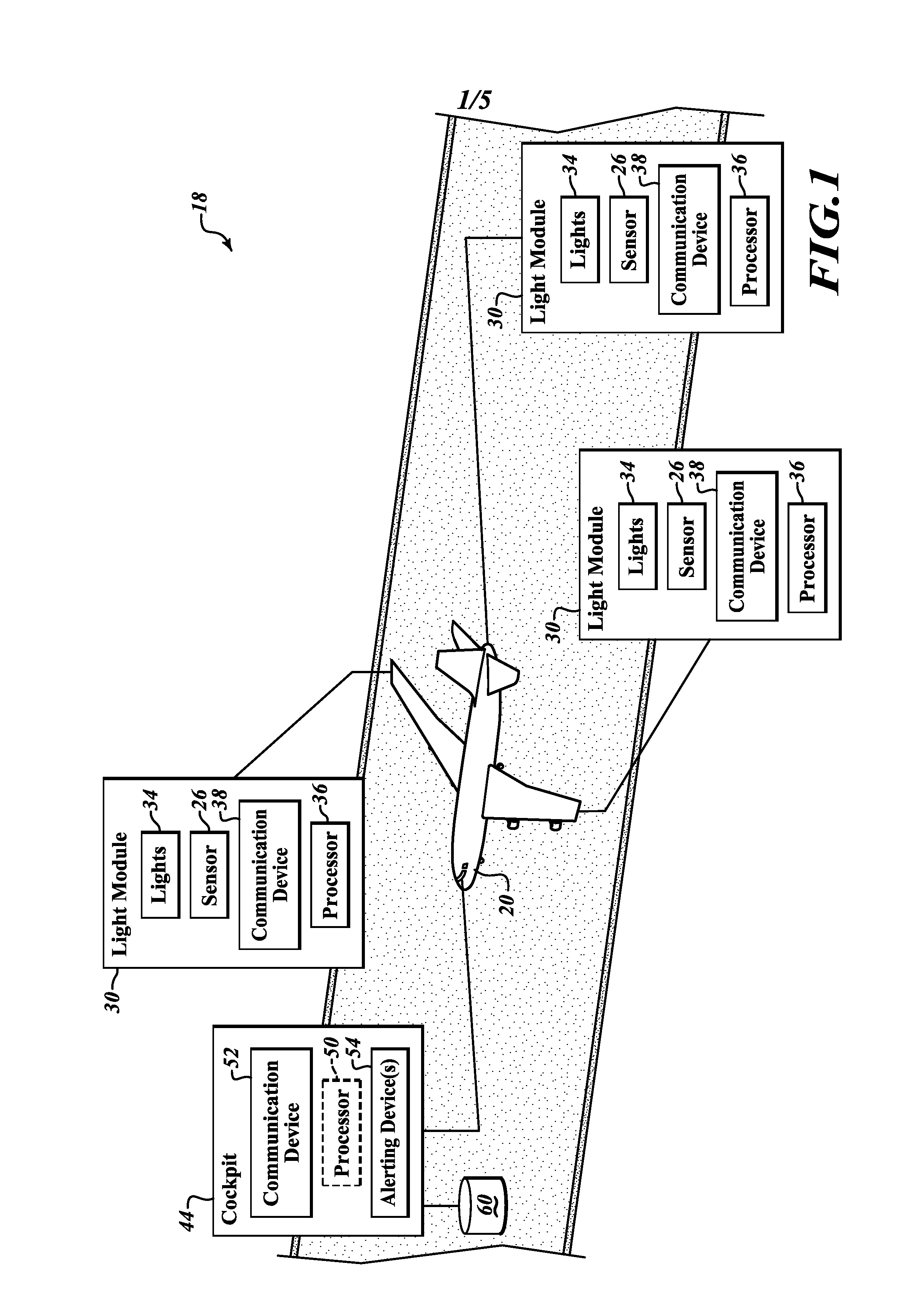
[0011]In one embodiment, as shown in FIG. 1, an exemplary airport surface collision-avoidance system (ASCAS) 18 includes an aircraft 20 that includes an electrically and / or mechanically steerable sensor 26 (e.g., active sensor, radar, or passive sensor camera) included within aircraft light modules 30 or located at the other positions about the aircraft 20. The light modules 30 also include navigation / position lights 34, a processor 36, and a communication device 38. The sensors 26 are in communication via the communication device 38 (wired or wirelessly) to a user interface (UI) device 44.

[0012]In one embodiment, the UI device 44 includes a processor 50 (optional), a communication device (wired or wireless) 52, and an alerting device(s) 54. The UI device 44 provides audio and / or visual cues (e.g., via headphones, PC tablets, etc.) based on sensor-derived and processed information.

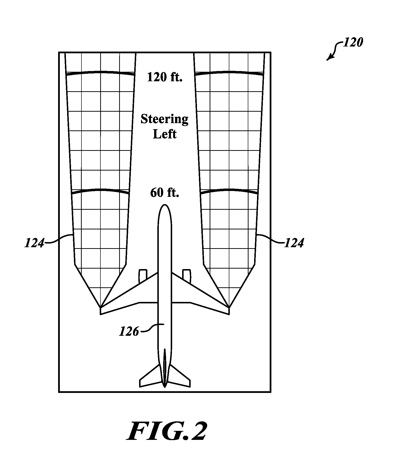
[0013]Based on information from the sensors 26, the UI device 44 provides some or all of the following ...


PUM


Abstract

Systems and methods for adaptively steering radar beam patterns for coverage during aircraft turns. The radar sensor system is mechanically or electrically steered to alter the radar sensor's beam pattern in order to adapt the radar sensor's field of view (FOV) to cover the area of anticipated aircraft wingtip trajectory. The anticipated trajectory is derived, for example, from the aircraft groundspeed, acceleration, heading, turn rate, tiller position, attitude, taxi clearance, etc.

Description

PRIORITY CLAIM[0001]This application claims the benefit of U.S. Provisional Application Ser. No. 61 / 653,297, filed May 30, 2012, the contents of which are hereby incorporated by reference. This application also claims the benefit of U.S. Provisional Application Ser. No. 61 / 706,632, filed Sep. 27, 2012, the contents of which are hereby incorporated by reference.BACKGROUND OF THE INVENTION[0002]Currently there exists an expensive safety problem of aircraft wingtips clipping obstacles (e.g., 2011 Paris Air Show, an A380 accident in which a wing hit a building; 2012 Chicago O'Hare accident in which a Boeing 747 cargo aircraft's wing clipped an Embraer 140's rudder; 2011 Boston Logan Int. Airport, a Boeing 767 struck a horizontal stabilizer of a Bombardier CRJ900, etc.). Some solutions focus on object detection by radar sensors placed at the wingtips and information about these potential obstacles is presented to the pilot on a human-machine interface (e.g., head-up, head-down, or head-m...

Claims


Application Information

Patent Timeline
Patent Type & Authority Applications(United States)
IPC IPC(8): G01S13/93G01S13/66G01S13/931G01S13/934
CPCG01S13/66G01S13/93B64C25/42B64D43/00B64D45/00G01C23/00G01S13/765G01S13/931G08G5/045G08G5/065G01S13/934G01S2013/9329G01S7/04B60Q9/008G08G5/04
Inventor DUSIK, MATEJVASEK, JIRIKIRK, JAMES C.VACANTI, DAVID C.MAGULA, FILIP
Owner HONEYWELL INT INC
Why Eureka
Try Eureka