
Antenna device

a technology of antenna device and antenna body, which is applied in the direction of resonant antenna, elongated active element feed, protective material radiating elements, etc., can solve the problem and achieve the effect of increasing the size of the antenna device and maximising the antenna performan

Inactive Publication Date: 2014-03-27
ALPS ALPINE CO LTD
View PDF2 Cites 2 Cited by
  • Summary
  • Abstract
  • Description
  • Claims
  • Application Information

AI Technical Summary

Benefits of technology

The present invention describes an antenna device that can be placed on top of a vehicle. The design of the antenna allows the only the surface of the device to be used for transmission, resulting in better performance without increasing the size of the device.

Problems solved by technology

However, such an antenna device 935 in the related art has problems as described below.
In addition, conversely, in case of trying to increase the antenna radiation element 923 such that the performance is not decreased, there is a problem in that it is inevitable to increase the size of the antenna device 935 by as much as the size of the plurality of mounting terminals 927.

Method used


Image

  • Antenna device
  • Antenna device
  • Antenna device

Examples


embodiments

[0017]Hereafter, the embodiments according to the present invention will be described with reference to the drawings.

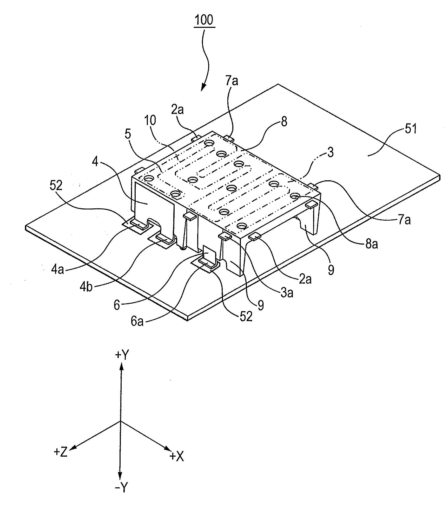
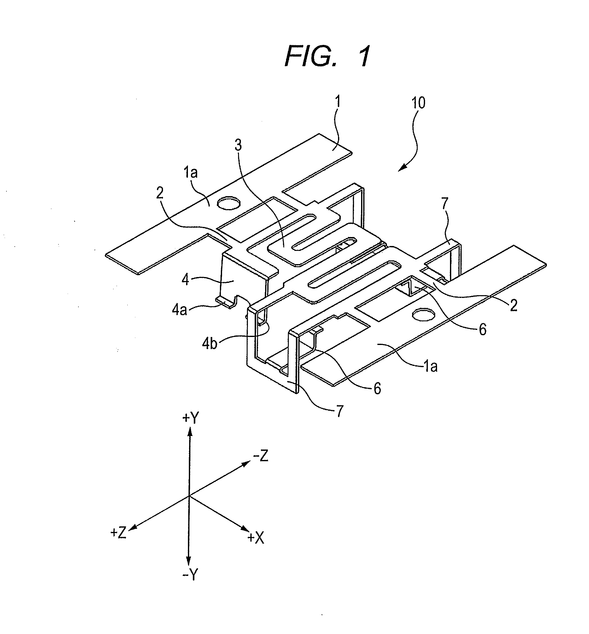
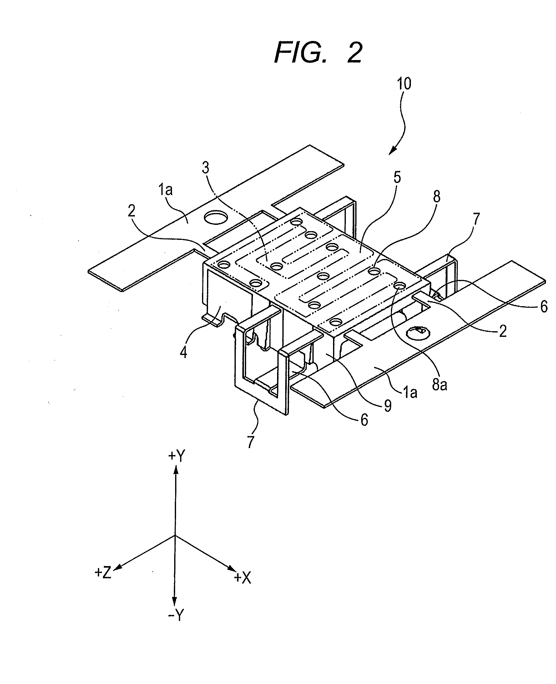
[0018]An antenna device in the embodiment of the present invention is the antenna device manufactured based on an antenna member formed of metal. FIG. 1 illustrates the antenna member in the process of manufacturing the antenna device in the embodiment of the present invention, and is a perspective view of the antenna member before the insert molding after the bending process. FIG. 2 is a perspective view illustrating the antenna device after the insert molding of the resin with respect the antenna member in FIG. 1. FIG. 3 is a perspective view illustrating the antenna device after cutting and removing of the connection section with respect to the insert molded antenna member in FIG. 2. In addition, FIG. 4A and FIG. 4B illustrate the antenna device in the embodiment of the present invention, FIG. 4A is a plan view and FIG. 4B is a cross-sectional view seen along the I...


PUM


Abstract

An antenna device can be placed on an insulation substrate having a wiring pattern and has an antenna member including an antenna radiation element, a mounting terminal, a power supply terminal formed continuously to the antenna radiation element, and the antenna member is formed by an insert molding with resin. The antenna device includes; a top surface portion that is parallel with respect to the surface of the insulation substrate when the device is placed on the insulation substrate, and a leg portion that is orthogonal with respect to the surface of the insulation substrate when the device is placed on the insulation substrate. The antenna radiation element is disposed on the top surface portion, and the mounting terminal and the power supply terminal are disposed only on the leg portion.

Description

CLAIM OF PRIORITY[0001]This application claims benefit of Japanese Patent Application No. 2012-214750 filed on Sep. 27, 2012, which is hereby incorporated by reference in its entirety.BACKGROUND[0002]1. Field of the Disclosure[0003]The present disclosure relates to an antenna device, particularly to an antenna device formed from insert molding with resin.[0004]2. Description of the Related Art[0005]In the related art, as an antenna device that uses an antenna radiation element made of a sheet of metal plate is used for a wireless LAN (Local Area Network; a GPS (Global Positioning System) in mobile equipment or a camera. In such an antenna device, an antenna device having a plurality of mounting terminals for supporting the antenna radiation element, and the antenna radiation element and the plurality of mounting terminals integrated by resin has been proposed.[0006]For example, an antenna device 935 illustrated in FIG. 5A and FIG. 5B, and disclosed in Japanese Unexamined Patent Appl...

Claims


Application Information

Patent Timeline
Patent Type & Authority Applications(United States)
IPC IPC(8): H01Q1/38
CPCH01Q1/38H01Q1/36H01Q1/40H01Q9/42
Inventor AZUMA, TOSHIYUKIMATSUZAKI, SATORUCHIDA, SATORU
Owner ALPS ALPINE CO LTD
Learn More