

Antenna device
a technology of antenna and ground plane, applied in the structure of radiating elements, elongated active elements, resonance antennas, etc., can solve the problems of deteriorating antenna performance, increasing unstable factors, and still remaining in conventional techniques, so as to achieve maximum antenna performance, high degree of freedom of installation, and suppress the effect of high-frequency current diffused to the ground plan
- Summary
- Abstract
- Description
- Claims
- Application Information
AI Technical Summary
Benefits of technology
Problems solved by technology
Method used
Image

Examples
examples
[0063]Next, a description will be given of the results of evaluation of the practically manufactured antenna device of the present embodiment in the present embodiment with reference to FIGS. 7 to 11.
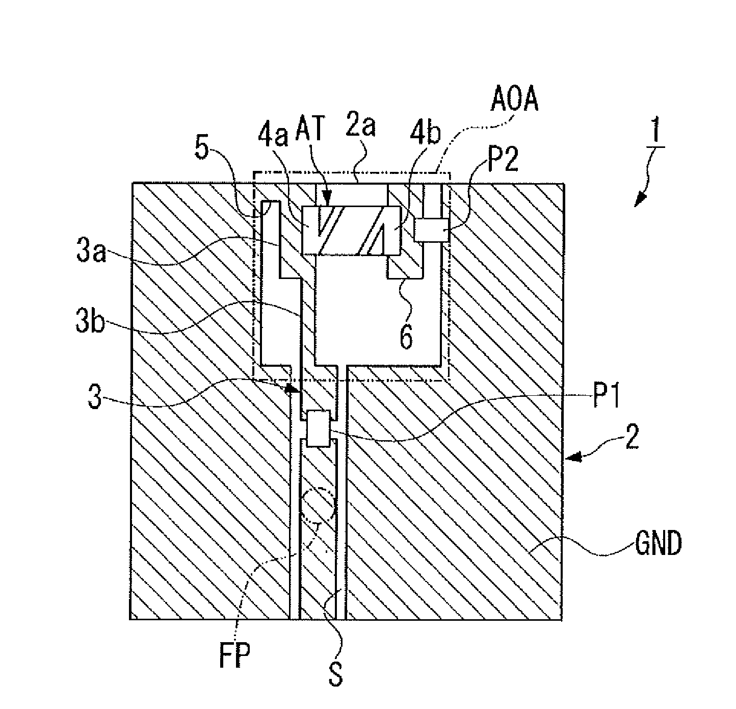
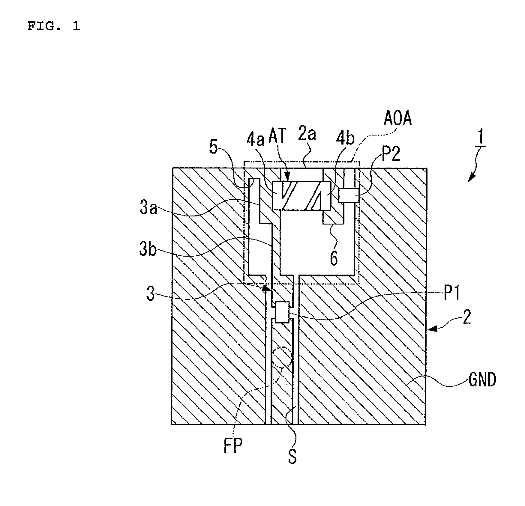
[0064]Firstly, the substrate main body (2) having one side (2a) of 100 mm and a side perpendicular to the one side (2a) of 50 mm was made in the present embodiment. At this time, a 4.2 nH inductor was used as the first passive element (P1) and a 0.3 pF capacitor was used as the second passive element (P2). Furthermore, the power feeding point (FP) was provided at substantially the center of the substrate main body (2).
[0065]The results of return loss in the present embodiment are shown in FIG. 8. Also, the radiation pattern of an antenna device in the present embodiment is shown in FIG. 9. Note that the direction along which one side (2a) of the substrate main body (2) extends is defined as the Y direction, the direction along which the power feeding pattern (3) extends is defined as th...
PUM
 Abstract
Description
Claims
Application Information