
Antenna device

a technology of antenna and ground plane, which is applied in the direction of antenna equipment with additional functions, antenna details, antennas, etc., can solve the problems of inability to display sufficient antenna performance and limited space (antenna-occupied area) which can be used as antennas, and achieve maximum antenna performance, high degree of freedom of installation, and suppressed high-frequency current diffused to the ground plane

Inactive Publication Date: 2015-09-22
MITSUBISHI MATERIALS CORP
View PDF20 Cites 4 Cited by
  • Summary
  • Abstract
  • Description
  • Claims
  • Application Information

AI Technical Summary

Benefits of technology

The present invention provides an antenna device that includes a dielectric antenna element connected to a power feeding pattern and a ground connection pattern, which helps to suppress the flow of high-frequency current and achieve high antenna performance even in a small antenna-occupied area. The device also provides a degree of freedom for installation.

Problems solved by technology

However, when a dielectric antenna is actually mounted as an antenna element onto a substrate, a space (antenna-occupied area) which can be used as an antenna is often limited by taking into consideration size reduction of equipment.
Consequently, sufficient antenna performance cannot be exhibited by the influence of the ground around the periphery of the antenna element.

Method used


Image

  • Antenna device
  • Antenna device
  • Antenna device

Examples


examples

[0064]Next, a description will be given of the results of evaluation of the practically manufactured antenna device of the present embodiment in the present embodiment with reference to FIGS. 7 to 11.

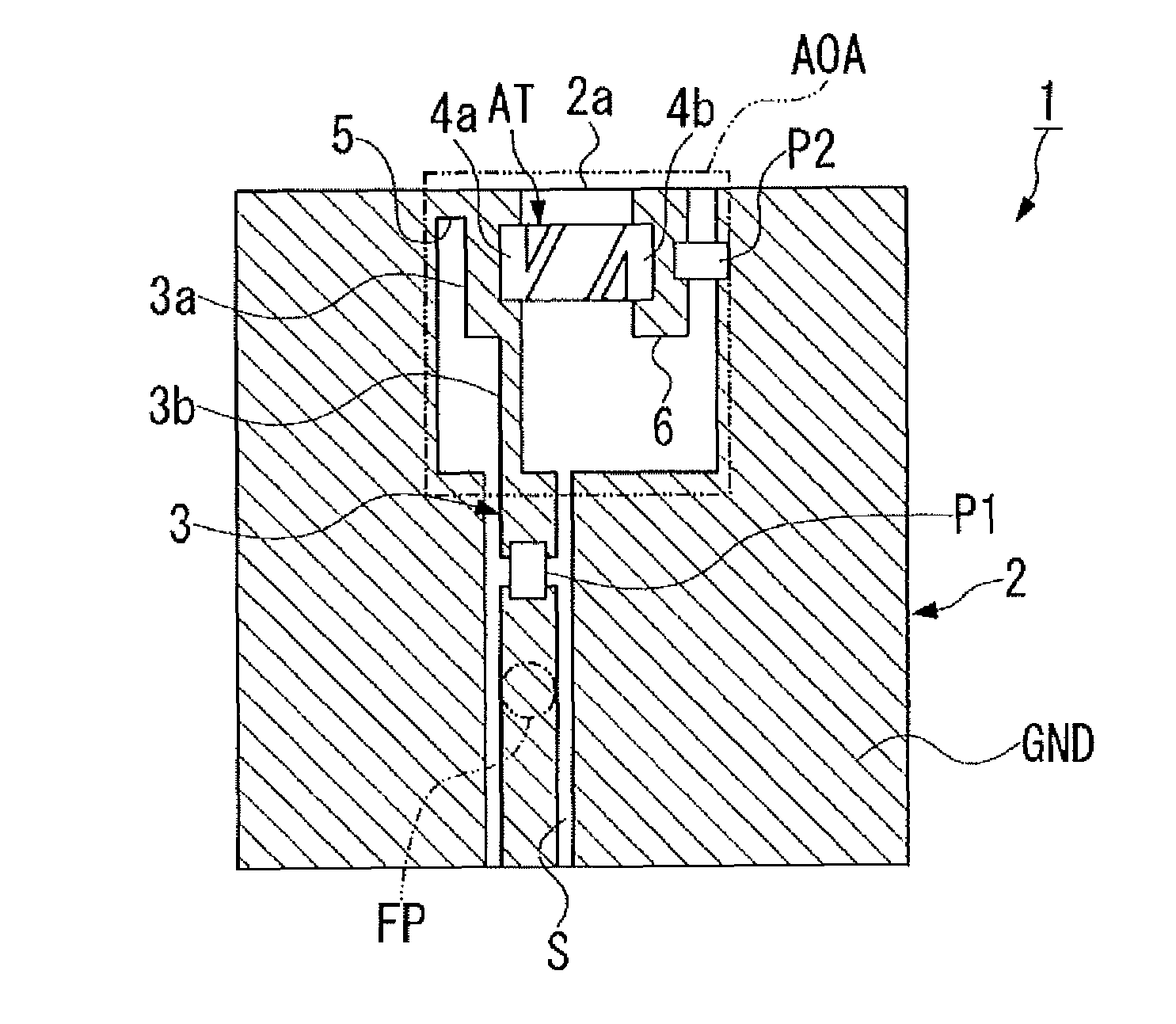
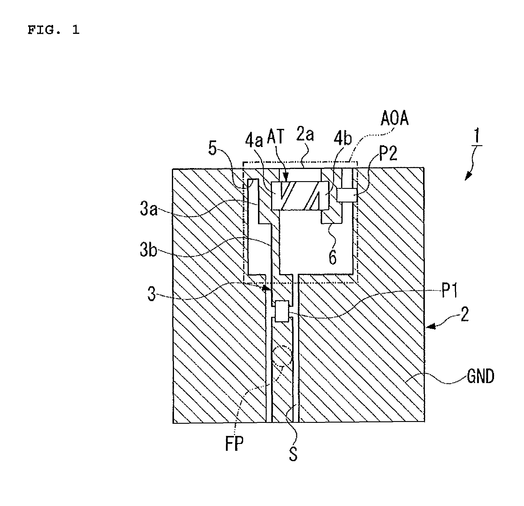
[0065]Firstly, the substrate main body (2) having one side (2a) of 100 mm and a side perpendicular to the one side (2a) of 50 mm was made in the present embodiment. At this time, a 4.2 nH inductor was used as the first passive element (P1) and a 0.3 pF capacitor was used as the second passive element (P2). Furthermore, the power feeding point (FP) was provided at substantially the center of the substrate main body (2).

[0066]The results of return loss in the present embodiment are shown in FIG. 7. Also, the radiation pattern of an antenna device in the present embodiment is shown in FIG. 8. Note that the direction along which one side (2a) of the substrate main body (2) extends is defined as the Y direction, the direction along which the power feeding pattern (3) extends is defined as th...


PUM


Abstract

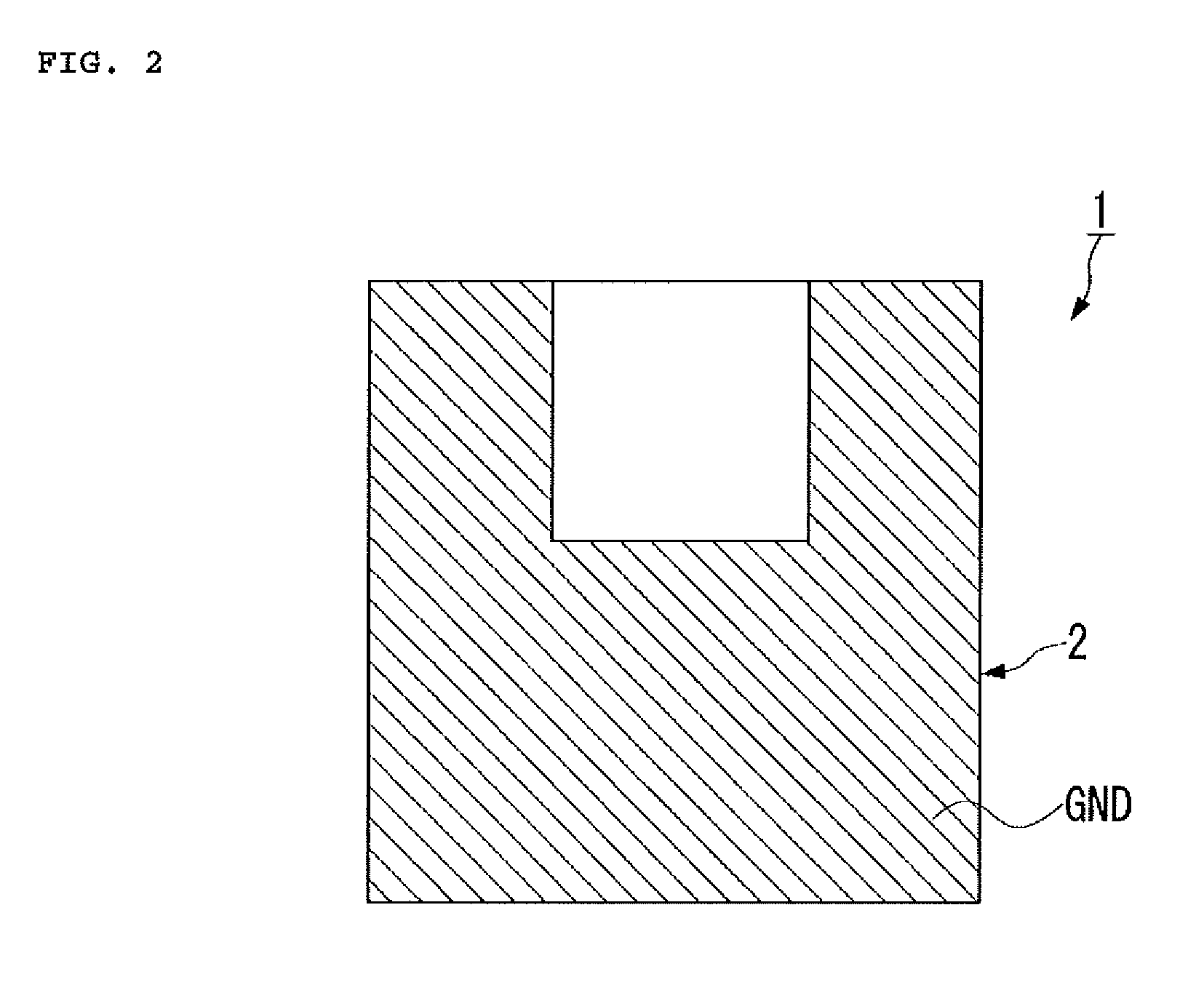
Provided is an antenna device that is capable of ensuring sufficient antenna performance by maximally utilizing a limited antenna occupied area. The antenna device is provided with a substrate main body (2); a ground plane (GND) that is formed on the substrate main body; an antenna-occupied area (AOA) that is provided in contact with one side (2a) of the substrate main body; a slit section (S) that is bored in the ground plane so as to extend from this area in the direction opposite to the one side (2a) of the substrate main body; a power feeding pattern (3) that is formed so as to extend into the slit section, provided with a power feeding point at the base end side, and connected with a first passive element (P1) halfway while the tip end side extends into the antenna-occupied area toward the one side of the substrate main body; an antenna element (AT) of a dielectric antenna that is connected to the tip end of the power feeding pattern and positioned along the one side of the substrate main body; a second passive element (P2) that is connected between the antenna element (AT) and the adjoining ground plane; and a ground connection pattern (5) for connecting the tip end of the power feeding pattern with the ground plane.

Description

CROSS-REFERENCE TO RELATED APPLICATIONS[0001]This application claims priority to PCT International Application No. PCT / JP2011 / 006467 filed Nov. 21, 2011, which claims the benefit of Japanese Patent Application No. 2010-267804 filed Nov. 30, 2010, the entire contents of the aforementioned applications are hereby incorporated herein by reference.BACKGROUND OF THE INVENTION[0002]1. Field of the Invention[0003]The present invention relates to an antenna device using a dielectric antenna.[0004]2. Description of the Related Art[0005]Conventionally, in communication equipment, a surface mounting antenna using a dielectric, i.e., a dielectric antenna has been used as one of antenna elements mounted onto a wireless circuit substrate. In the dielectric antenna, a radiation electrode for antenna operation is provided on a dielectric substrate. Conventionally, an open-end type antenna such as a monopole antenna or an inverse F-type antenna using this dielectric antenna has been a mainstream.[00...

Claims


Application Information

Patent Timeline
Patent Type & Authority Patents(United States)
IPC IPC(8): H01Q9/04H01Q1/38H01Q9/36H01Q1/22H01Q9/42
CPCH01Q9/42H01Q1/38H01Q1/2283H01Q9/36H01Q1/24H01Q1/46
Inventor YUKIMOTO, SHINSUKESAITO, RYO
Owner MITSUBISHI MATERIALS CORP
Learn More