
Dual-band antenna

a dual-band antenna and transceiver technology, applied in the direction of antennas, antenna details, antenna earthings, etc., can solve the problems of increasing the fabrication process, unable to produce the dual-band receiving/transmitting effect in practice, and regarded as a single-frequency antenna, so as to achieve optimal impedance matching, eliminate the limitation of the ground path of the conventional inverted-f antenna, and achieve maximum antenna radiation performance

Inactive Publication Date: 2008-08-21
MITAC TECH CORP
View PDF10 Cites 13 Cited by
  • Summary
  • Abstract
  • Description
  • Claims
  • Application Information

AI Technical Summary

Benefits of technology

[0010]The advantage of the present invention is using the currently available design principle of an inverted-F antenna to alter the structure of the ground path, so as to re-allocate the current feeding path. Accordingly, the limitation on the structure of the ground path in the conventional inverted-F antenna can be eliminated. Meanwhile, an optimal impedance matching can be obtained by connection units of various structures together with appropriate feeding manners, so as to achieve the maximum performance of the antenna radiation.
[0011]The detailed features and advantages of the present invention will be described in detail in the following embodiments. Those skilled in the arts can easily understand and implement the content of the present invention. Furthermore, the relative objectives and advantages of the present invention are apparent to those skilled in the arts with reference to the content disclosed in the specification, claims, and drawings.
[0012]The above description of the content of the present invention and the following illustration of the embodiments are intended to demonstrate and explain the principle of the present invention and to provide

Problems solved by technology

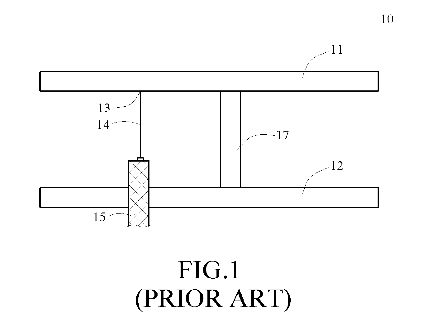
Therefore, the above design cannot produce the dual-band receiving / transmitting effect in practice, and can only be regarded as a single-frequency antenna.
However, as the interconnecting element is composed by three parts, the fabrication of the interconnecting element at least needs two solder joints, which increases the fabrication process, and is time and energy consuming.
Moreover, the increase of the solder joints also worsens the uncertainty of the product yield and makes it easy to couple a portion of the noises.
Additionally, in the above design, a ground path has two right-angled turns, which affects the transmission through the ground path, and makes it difficult to adjust the input / output impedance.
Such problem concerns the distance from the signal feeding end to the grounding unit, and can cause poor impedance matching.
Therefore, under the requirement of a short, small, light, and thin dual-band antenna, the structure of the dual-band antenna is very likely to be limited.
For example, in the above design, the dual-band transmission effect cannot be achieved effectively.

Method used


Image

  • Dual-band antenna
  • Dual-band antenna
  • Dual-band antenna

Examples


Embodiment Construction

[0021]The objectives, structures, features, and functions of the present invention will be illustrated in detail below accompanied with the embodiments.

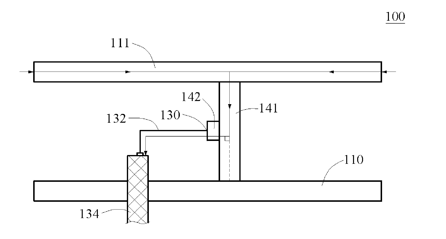
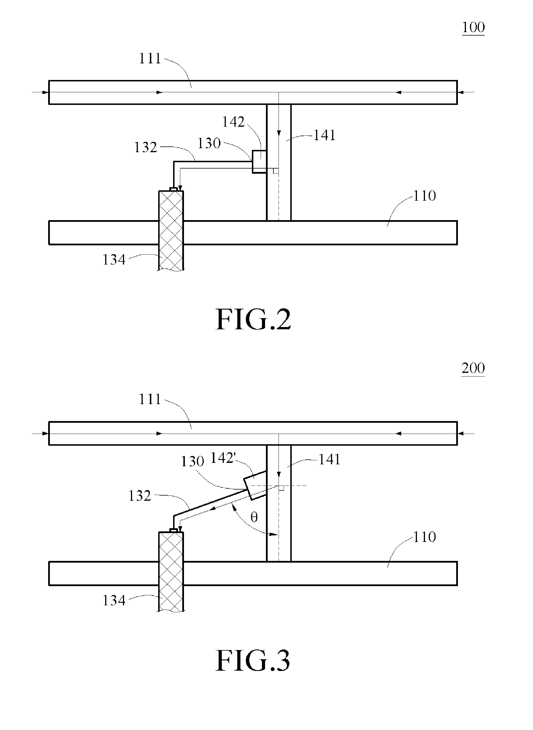
[0022]First, referring to FIG. 2, a side view of the first embodiment of the present invention is shown. In FIG. 2, the dual-band antenna 100 according to the first embodiment of the present invention has a signal resonance unit 111, a grounding unit 110 disposed opposite to the signal resonance unit 111, a connection unit, and a signal line 132.

[0023]The connection unit has a first connection element 141 and a second connection element 142. A signal feeding end 130 of the signal line 132 is connected to the second connection element 142 of the connection unit, and a circuit connection end 134 of the signal line 132 is connected to a wireless circuit device, so as to form a signal path.

[0024]One end of the first connection element 141 of the connection unit is perpendicularly connected to the signal resonance unit 111, and the other ...


PUM


Abstract

A dual-band antenna is provided, which includes a signal resonance unit, a grounding unit, a connection unit, and a signal line. The grounding unit is disposed opposite to the signal resonance unit. The connection unit has a first connection element and a second connection element, wherein one end of the first connection element is connected to the signal resonance unit and the other end of the first connection element is connected to the grounding unit, while one end of the second connection element is connected to one side of the first connection element. The signal line has a signal feeding end and a circuit connection end, wherein the signal feeding end is electrically connected to the second connection element, and the circuit connection end is electrically connected to a wireless circuit device.

Description

BACKGROUND OF THE INVENTION[0001]1. Field of Invention[0002]The present invention relates to a signal transceiver, and more particularly to a dual-band signal transceiver for radio signal transmission.[0003]2. Related Art[0004]In recent years, as people's demand on wireless communication is growing higher, the elements used in wireless communication have become the main trend for research and development work. In the field of wireless communication, antenna is an important element for receiving and transmitting signals. An antenna is a electrical coupling element or conducting system that can convert an electrical signal in the circuit to the electromagnetic energy in the space. When transmitting a signal, the antenna converts the electric energy of radio frequency into electromagnetic energy which is then radiated to the surrounding environment. When receiving a signal, the antenna receives the electromagnetic energy radiation and converts it into the electric energy of radio frequ...

Claims


Application Information

Patent Timeline
IPC IPC(8): H01Q1/48
CPCH01Q9/045H01Q5/371H01Q9/42
Inventor CHENG, YU-CHIANGCHANG, PING-CHENGCHOU, CHENG-ZENG
Owner MITAC TECH CORP
Learn More