
Built-in antenna for portable terminal

a portable terminal and built-in antenna technology, which is applied in the structural form of radiating elements, resonant antennas, substantially flat resonant elements, etc., can solve the problems of reducing the portability of the terminal, difficult to achieve the maximum performance of the radiator, and prone to external effects, so as to prevent the deterioration of the antenna performance

Inactive Publication Date: 2008-03-27
SAMSUNG ELECTRONICS CO LTD
View PDF1 Cites 5 Cited by
  • Summary
  • Abstract
  • Description
  • Claims
  • Application Information

AI Technical Summary

Benefits of technology

[0016]An object of the present invention is to substantially solve at least the above problems and / or disadvantages and to provide at least the advantages below. Accordingly, an object of the present invention is to provide a built-in antenna for a portable terminal configured to prevent deterioration of antenna performance caused by external interference.
[0017]Another object of the present invention is to provide a built-in antenna for a portable terminal configured to achieve maximum antenna performance by installing a conductor at a built-in antenna and thus reducing fluctuation of VSWR caused by external interference.
[0018]Still another object of the present invention is to provide a built-in antenna for a portable terminal configured to facilitate impedance matching for coupling and to prevent deterioration of a radiation characteristic caused by external interference.

Problems solved by technology

An antenna, a rod antenna (or a whip antenna), and a helical antenna that protrude outwardly from a terminal are susceptible to damage from dropping, and reduce portability of the terminal.
However, since feeding and grounding must be simultaneously performed, it is difficult to match an impedance, which makes it difficult to achieve maximum performance of the radiator.
However, the PILA is mounted to a terminal, and is susceptible to an external effect such as a user's finger touch.

Method used


Image

  • Built-in antenna for portable terminal
  • Built-in antenna for portable terminal
  • Built-in antenna for portable terminal

Examples


Embodiment Construction

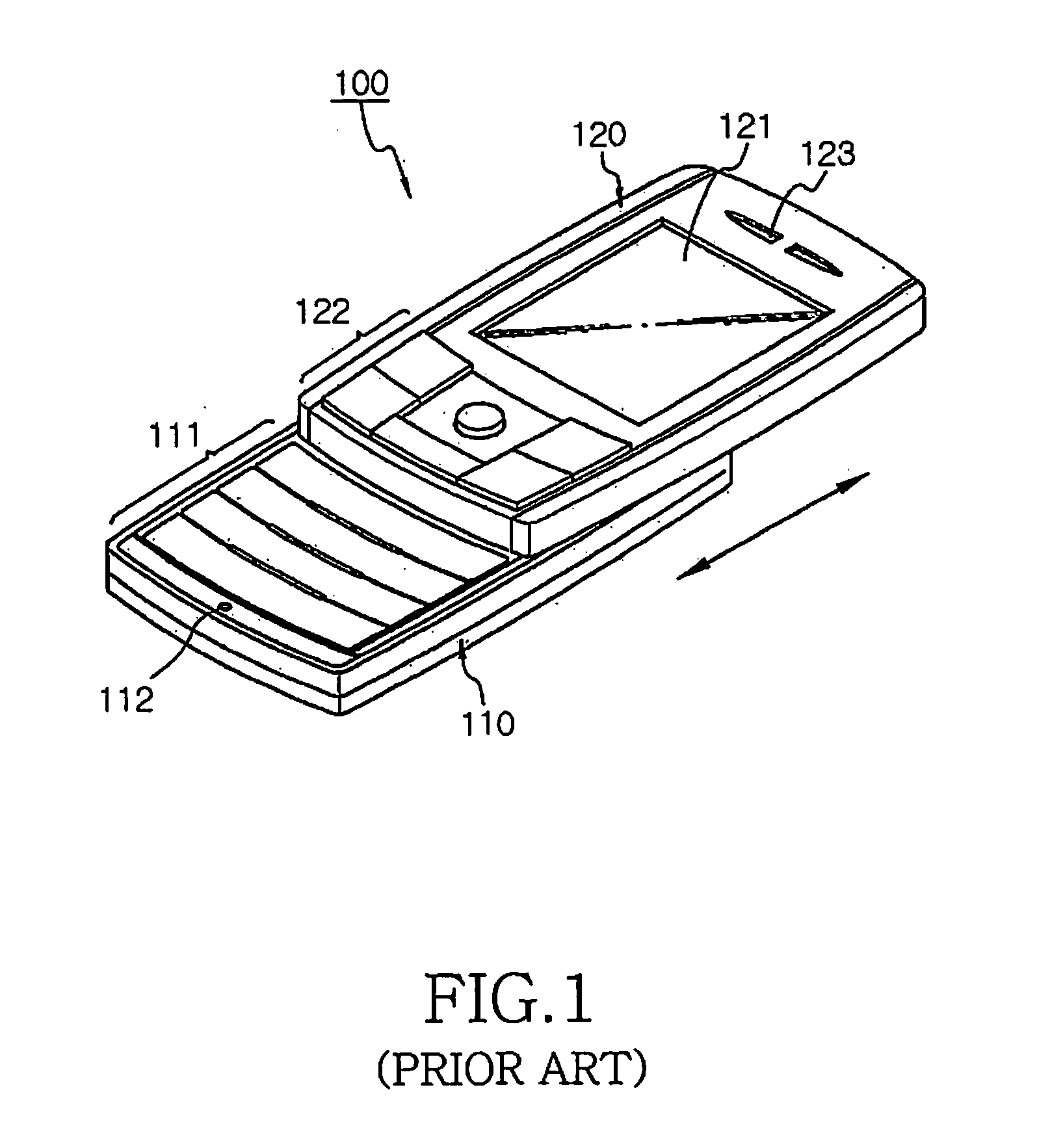
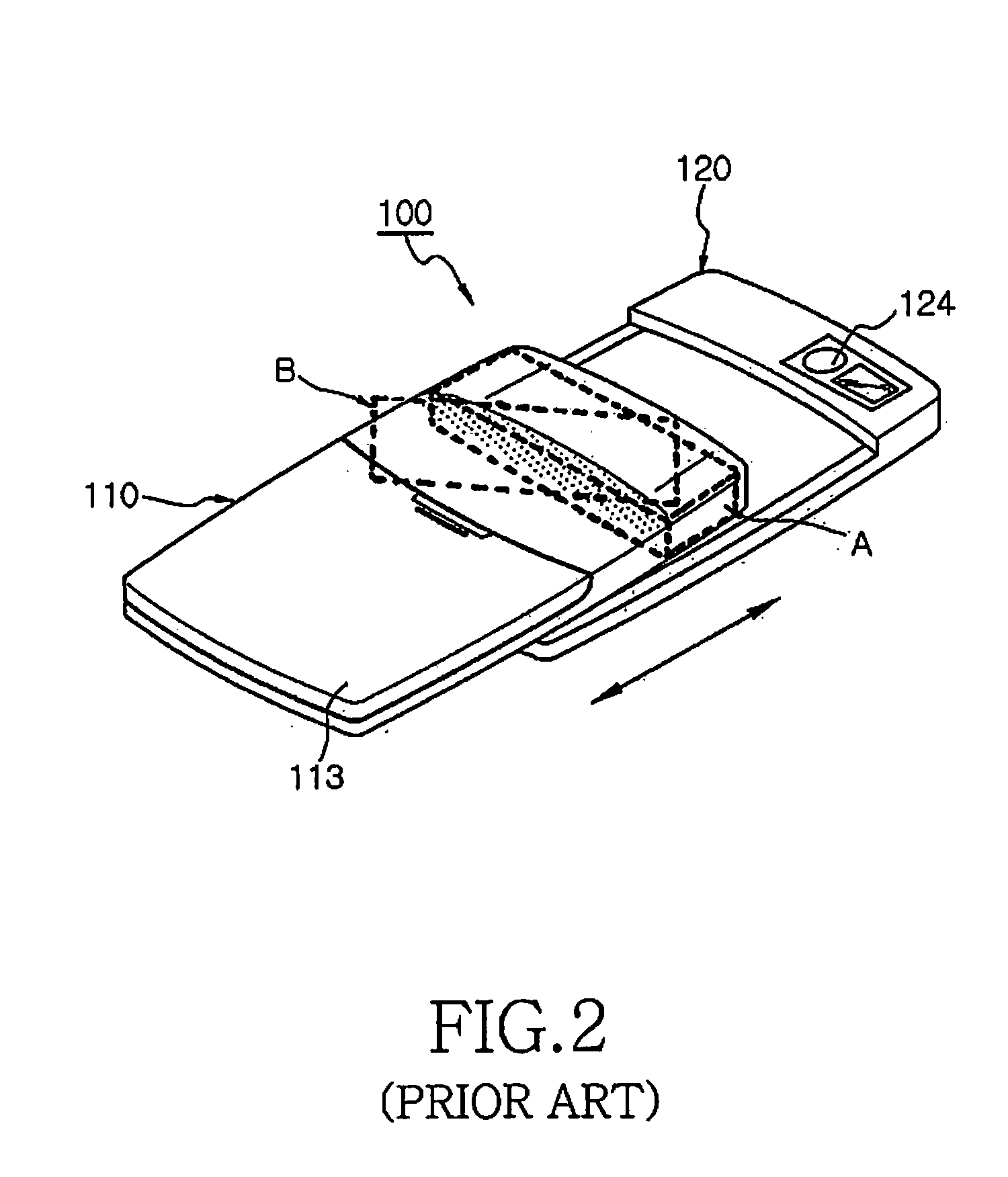
[0030]Preferred embodiments of the present invention will be described herein below with reference to the accompanying drawings. In the following description, well-known functions or constructions are not described in detail since they would obscure the invention in unnecessary detail. Since a built-in antenna according to the present invention is also applied to part A of FIG. 2, the description thereof will be omitted.

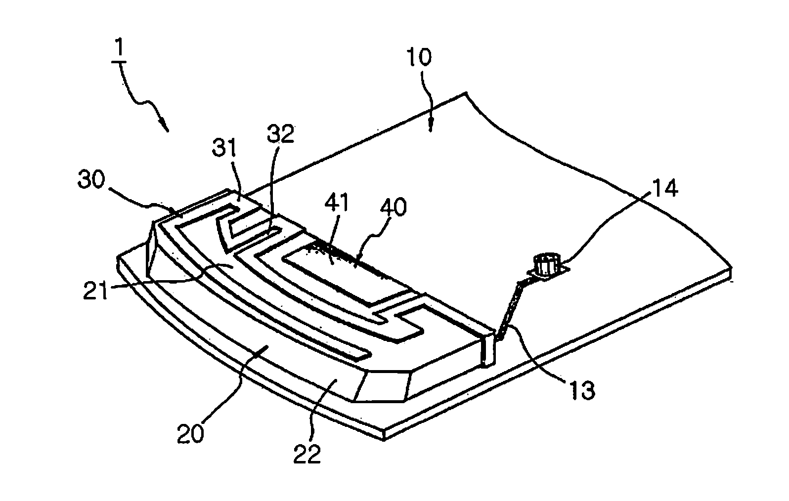
[0031]FIG. 3 is an exploded perspective view of a built-in antenna 1 according to the present invention. The built-in antenna 1 includes a main board 10 which is a Radio Frequency (RF) board installed in a main body of a terminal, an antenna carrier 20 installed on the main board 10 and having a predetermined height, an antenna radiator 30 installed on a top surface 21 of the antenna carrier 20, and a conductor 40 installed at the antenna carrier 20 and installed separately from the antenna radiator 30.

[0032]Various electronic function groups (not shown) of the termi...


PUM


Abstract

Provided is a built-in antenna for a portable terminal. The built-in antenna includes a main board including a feed pad electrically connected to a Radio Frequency (RF) connector, and a ground layer with a predetermined area; an antenna carrier installed on the main board and having a predetermined height; an antenna radiator installed at the antenna carrier and having a predetermined shape, the antenna radiator being electrically connected to the feed pad; and a conductor installed at a predetermined portion of the antenna carrier, the conductor being electrically connected to the ground layer.

Description

PRIORITY[0001]This application claims priority under 35 U.S.C. §119(a) to an application filed in the Korean Intellectual Property Office on Sep. 25, 2006 and allocated Serial No. 2006-92715, the contents of which are incorporated herein by reference.BACKGROUND OF THE INVENTION[0002]1. Field of the Invention[0003]The present invention relates generally to a built-in antenna module embedded in a portable wireless terminal, and in particular, to a built-in antenna module for a portable wireless terminal configured to improve a radiation characteristic of a Planar Inverted-F Antenna (PIFA), and antenna performance such as reducing the Specific Absorption Rate (SAR).[0004]2. Description of the Related Art[0005]Recently, terminals with various functions and designs are being introduced. Consumers' demands for smaller, lighter and slimmer terminals with various functions are increasing. To meet such consumers' demands, terminal providers are focused on reducing the volume of a terminal wh...

Claims


Application Information

Patent Timeline
Patent Type & Authority Applications(United States)
IPC IPC(8): H01Q1/22H01Q9/04
CPCH01Q1/243H01Q19/005H01Q9/0421H01Q9/0407
Inventor SUH, YOUNG-HOON
Owner SAMSUNG ELECTRONICS CO LTD
Learn More