Contactless Generator, Component Therein and Application Thereof

a generator and contactless technology, applied in the field of generators, can solve the problems of increasing the effort a rider needs to apply, increasing the cost of operation,

Inactive Publication Date: 2014-03-27
SUNRISING ECO FRIENDLY TECH
View PDF11 Cites 15 Cited by
  • Summary
  • Abstract
  • Description
  • Claims
  • Application Information

AI Technical Summary

Benefits of technology

[0013]An induction rotor component in accordance with the present invention comprises a shaft and a magnetic module. The shaft has a surface and a longitudinal axis. The magnetic module is mounted on the surface of the shaft and positioned near a moving metallic object. The magnetic module is subjected to an active force from an ext

Problems solved by technology

For example, because usage of battery is sometimes inconvenient in bicycle and vehicle fields, contact generators or hub dynamos are common in the market.
However, contact generators or hub dynamos have the following constraints and inconveniences.
Because the electrical energy is produced by contacting

Method used


Image

  • Contactless Generator, Component Therein and Application Thereof
  • Contactless Generator, Component Therein and Application Thereof
  • Contactless Generator, Component Therein and Application Thereof

Examples


Embodiment Construction

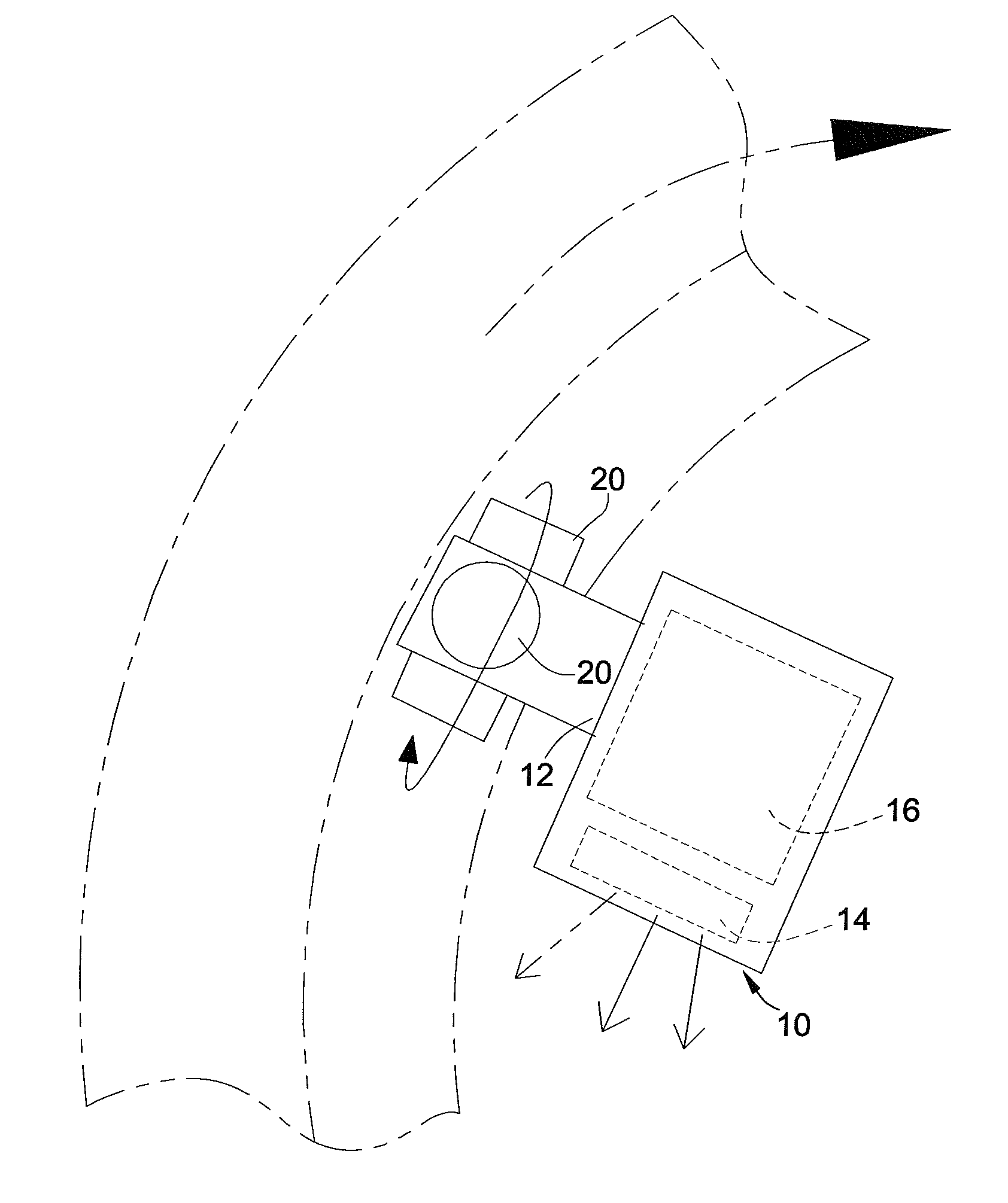
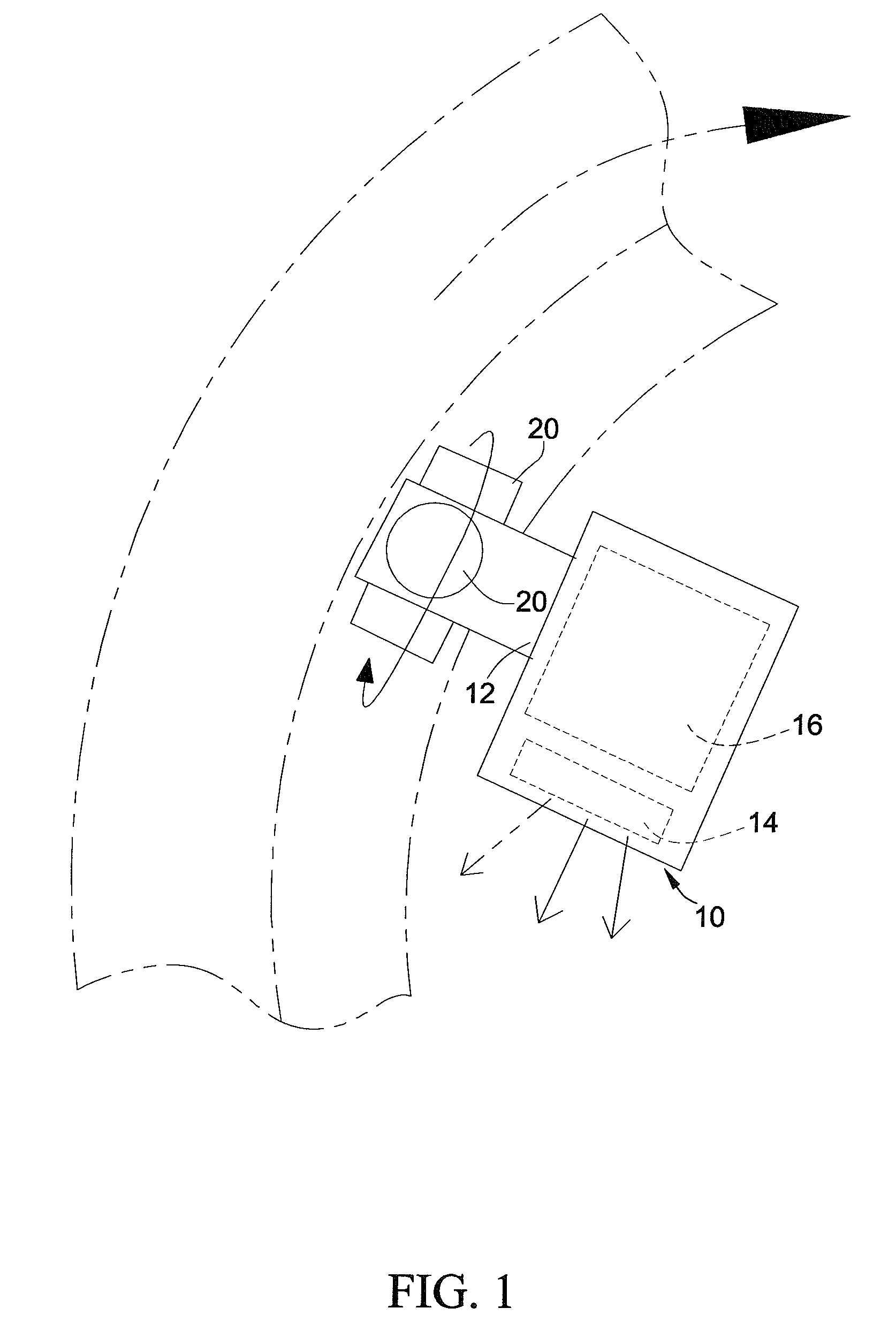
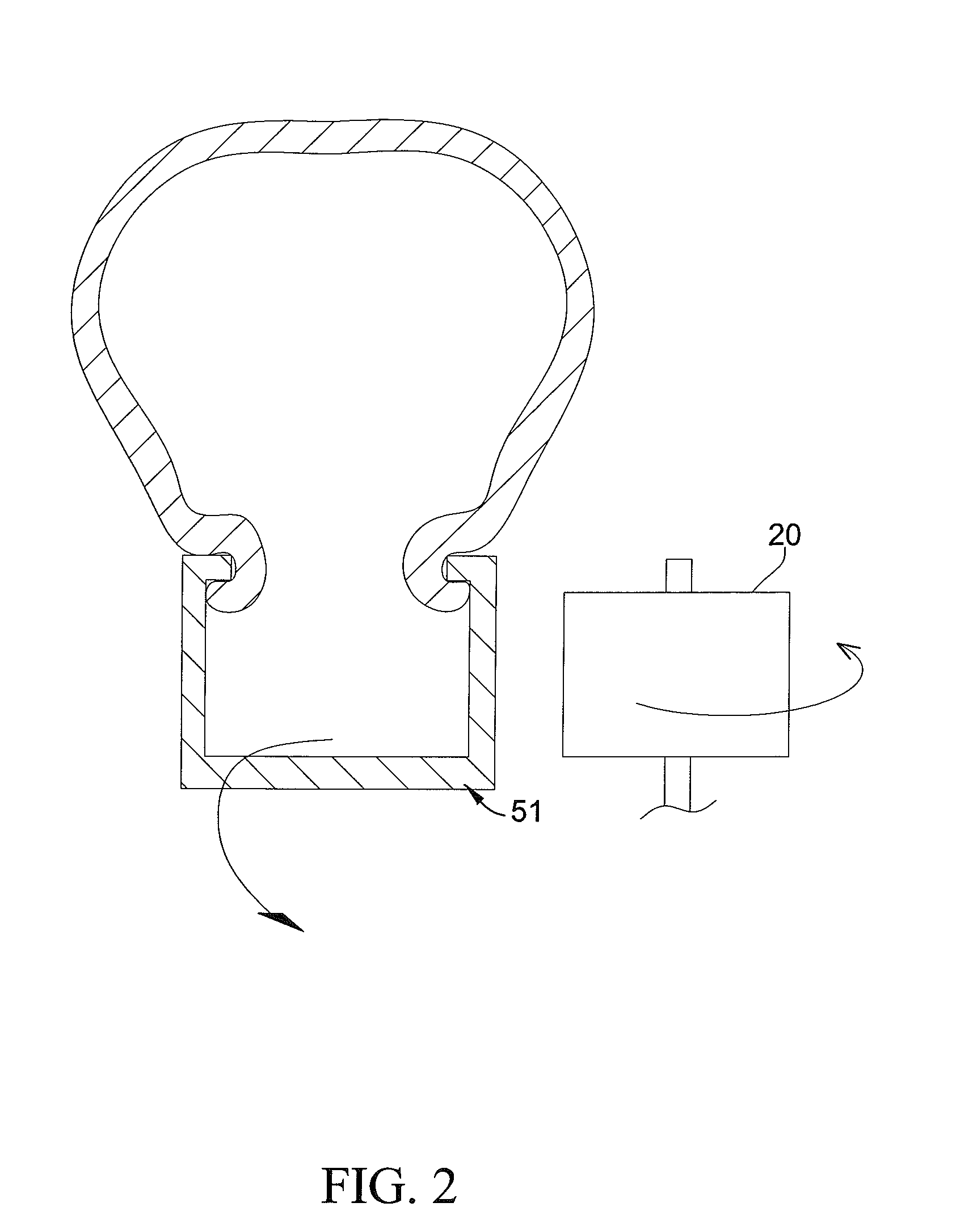
[0026]With reference to FIGS. 1 to 4 illustrating a contactless generator in accordance with an embodiment of the present invention, the contactless generator comprises a generating module (10) and a magnetic module (20). The generating module (10) has a rotator (12) and an energy converter (16). The rotator (12) is rotatable relative to the energy converter (16) or other components of the generating module (10). In this embodiment, the rotator (12) may be a shaft rotatably inserted into the energy converter (16). When the rotator (12) is rotated relative to the energy converter (16), the energy converter (16) converts mechanical energy of the rotator (12) when rotating into electricity by a converting means. The converting means in this embodiment is that the rotator (12) has a magnetic element aligned with the energy converter (16) and energy converter (16) has an induction coil. When the rotator (12) is rotated, the magnetic element is brought to rotate relative to the energy con...


PUM


Abstract

A contactless generator includes a generating module and a magnetic module. The generating module includes an energy converter and a rotator. The rotator has a surface and mechanical energy when rotating and is rotatable relative to the energy converter. The magnetic module is mounted on the surface of the rotator, aligned with the energy converter, and produces a intrinsic magnetic field. The intrinsic magnetic field is subjected to a contactless active force from an external contactless moving metallic object and drives the rotator to rotate. The energy converter converts mechanical energy of the rotator when rotating into electricity by a converting means.

Description

BACKGROUND OF THE INVENTION[0001]1. Field of Invention The present invention relates to a generator, and more particularly to a contactless generator, a component therein and an application thereof.[0002]2. Description of the Related Art[0003]Conventional generators generally convert mechanical energy into electrical energy. For example, because usage of battery is sometimes inconvenient in bicycle and vehicle fields, contact generators or hub dynamos are common in the market. However, contact generators or hub dynamos have the following constraints and inconveniences.[0004]1. With reference to FIG. 10, a contact generator (80) has a component (B) contacted with a surface of a rim (82) of a wheel (A). When the wheel (A) is rotated, the component (B) of the contact generator (80) is brought to rotate. Then the contact generator (80) converts mechanical energy of rotating into electrical energy. Because the electrical energy is produced by contacting the contact generator (80) with th...

Claims


Application Information

Patent Timeline
IPC IPC(8): B62J6/00F21L13/06H02K7/18
CPCB62J6/003F21L13/06H02K7/1853H02K7/11H02K7/1846B62J6/015
Inventor LIAO, KUANG YANG
Owner SUNRISING ECO FRIENDLY TECH
Why Eureka
Try Eureka