
Device for Monitoring Area Around Working Machine

a monitoring device and working machine technology, applied in the field of surround-based monitoring systems of working machines, can solve the problems of difficult recognition of directions, hardly grasped distance sense, and inability to recognize,

Inactive Publication Date: 2014-03-27
NIHON KENKI CO LTD
View PDF8 Cites 97 Cited by
  • Summary
  • Abstract
  • Description
  • Claims
  • Application Information

AI Technical Summary

Benefits of technology

The patent describes how to capture images of a moving workplace and show them on a computer screen. By arranging cameras at different points on the machine, we get a wide-angle look around it. This allows operators to see what they should pay attention to while driving or operating the machinery.

Problems solved by technology

The technical problem addressed in this patent is the difficulty in accurately determining the distance and direction of a person or object from a working machine using conventional camera images displayed on a monitor. This can make it difficult to safely operate the machine and can lead to unsafe work conditions. The patent proposes a solution using a system that captures images from cameras mounted on the machine and transforms them to create a virtual viewpoint image that can be displayed on a monitor. This virtual viewpoint image provides a more accurate representation of the machine's surroundings, allowing the operator to better assess the distance and direction of any personnel or material obstacles, and take appropriate action to prevent accidents and improve operability.

Method used


Image

  • Device for Monitoring Area Around Working Machine
  • Device for Monitoring Area Around Working Machine
  • Device for Monitoring Area Around Working Machine

Examples


Embodiment Construction

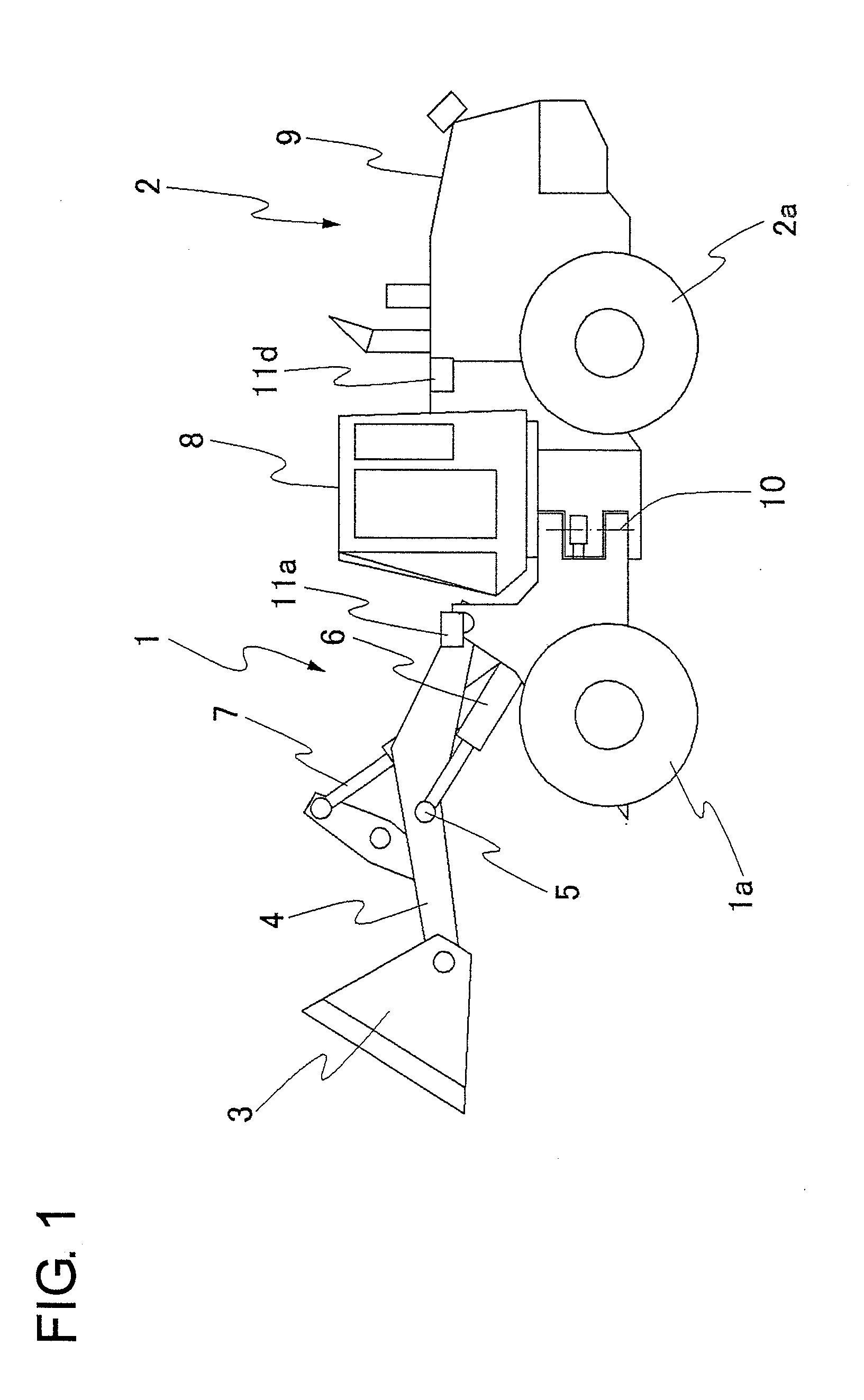
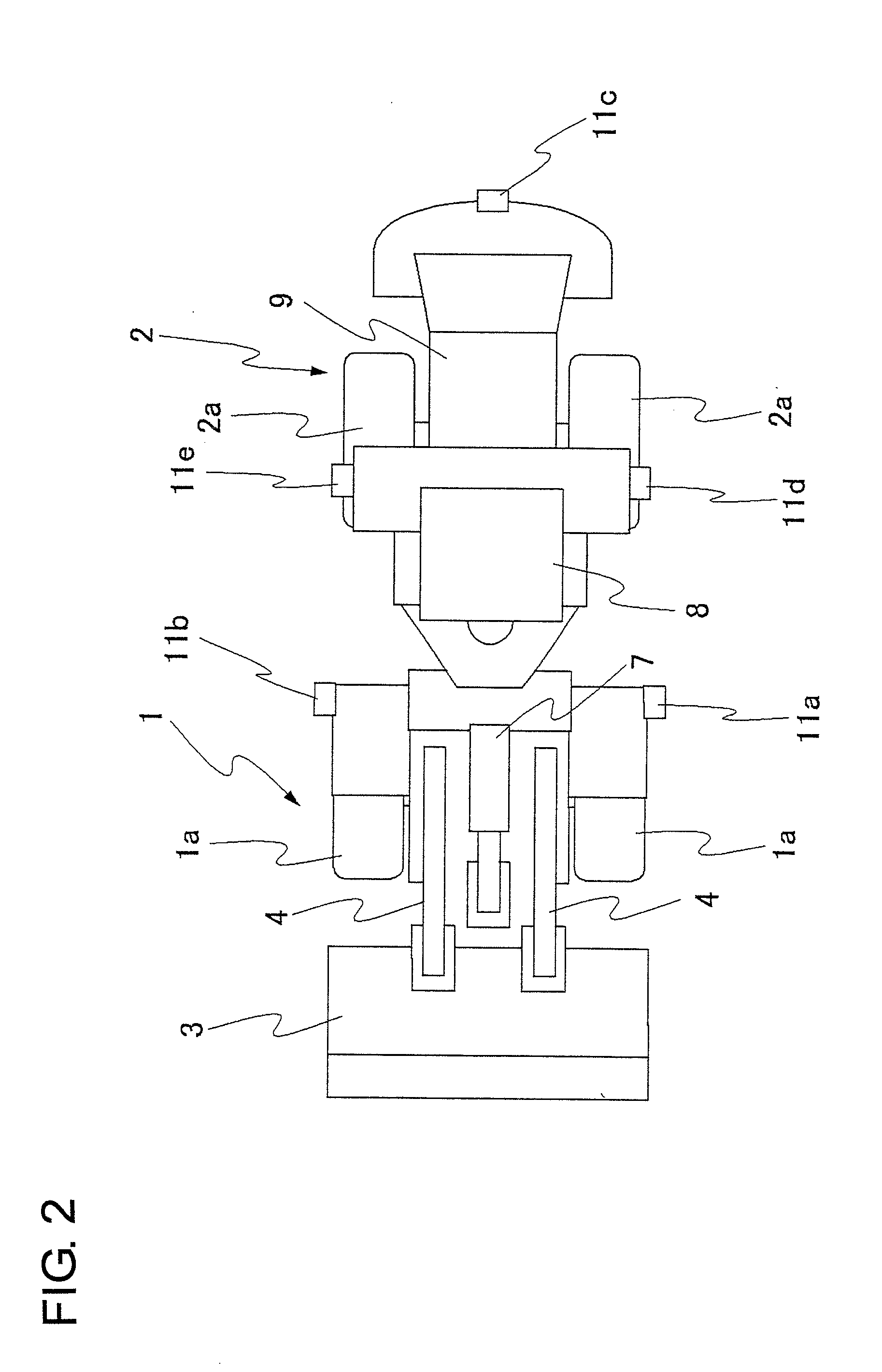
[0032]Embodiments of the present invention will hereinafter be described based on the drawings. First, the construction of an articulated wheel loader as an example of an articulated working machine is shown in FIGS. 1 to 3.

[0033]In FIGS. 1 and 2, numeral 1 designates a vehicle front section, and numeral 2 designates a vehicle rear section. The vehicle front section 1 has wheels la, and on its front part, a loader bucket 3 is mounted as a working means. This loader bucket 3 is connected to free ends of arms 4 via connecting pins 5, and is tiltable by a bucket cylinder 6 in an up-and-down direction about the connecting pins 5. Arm cylinders 7 are connected to the arms 4, and upon actuation of the arm cylinders 7, the loader bucket 3 moves up or down. The vehicle rear section 2 has wheels 2a, and on the vehicle rear section 2, an operator's cab 8 equipped internally with an operator's seat and various control means is arranged. At a position behind the operator's cab 8, an engine and ...


PUM


Abstract

Upon displaying, on a monitor, camera images obtained by cameras mounted on a vehicle front section and vehicle rear section, the vehicle rear section with an operator's cab mounted thereon is displayed as a fixed character image while the vehicle front section is displayed as a movable character image bendable relative to the fixed character image. Around a vehicle image displayed as described above, a composite bird's eye view image, which has been composed from individual bird's eye view images obtained by subjecting the camera images to coordinate transformation such that upper viewpoint images are formed is displayed, so that the individual bird's eye view images acquired from the cameras mounted on the vehicle front section are changed in display range when the vehicle front section and vehicle rear section are bent about a pivot pin.

Description


Claims


Application Information

Patent Timeline
Owner NIHON KENKI CO LTD
Features
  • Generate Ideas
  • Intellectual Property
  • Life Sciences
  • Materials
  • Tech Scout
  • Unparalleled Data Quality
  • Higher Quality Content
  • 60% Fewer Hallucinations
Learn More