Actuator

a technology of actuators and actuators, applied in the field of actuators, can solve the problems of bringing performance disadvantages, weights, and dimensions of actuators of small dimensions, and achieve the effects of reducing ohmic losses, short switching and movement times, and simple and elegan

Active Publication Date: 2014-04-03
ETO MAGNETIC GMBH
View PDF5 Cites 17 Cited by
  • Summary
  • Abstract
  • Description
  • Claims
  • Application Information

AI Technical Summary

Benefits of technology

[0019]The end result is that in a simple and elegant manner the present invention permits the magnetic field advantages of a plurality of coil devices (compared with an individual coil, for instance) in terms of the MSM drive element to be combined with an optimised flux-conducting structure, with reduced ohmic losses and heat generation, which in addition to design simplicity, enables short switching and movement times.

Problems solved by technology

The disadvantageous consequence of these influences is that the modules of the magnetic circuit must be dimensioned (unnecessarily) large, with resulting disadvantages in dimensions, weights, and costs.
In contrast, actuators of small dimensions would definitely bring with them performance disadvantages under these conditions, particularly in terms of undesirable heating and / or prolonged movement and switching times.

Method used


Image

  • Actuator
  • Actuator
  • Actuator

Examples


Embodiment Construction

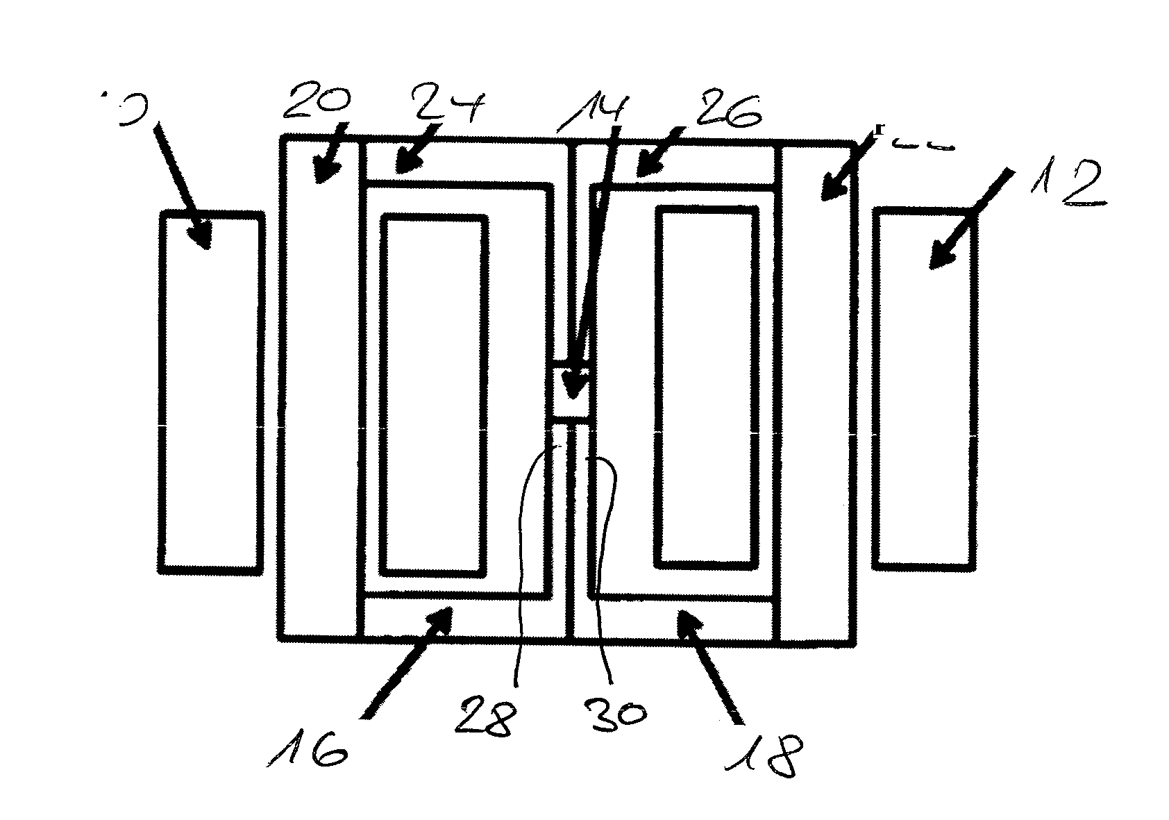
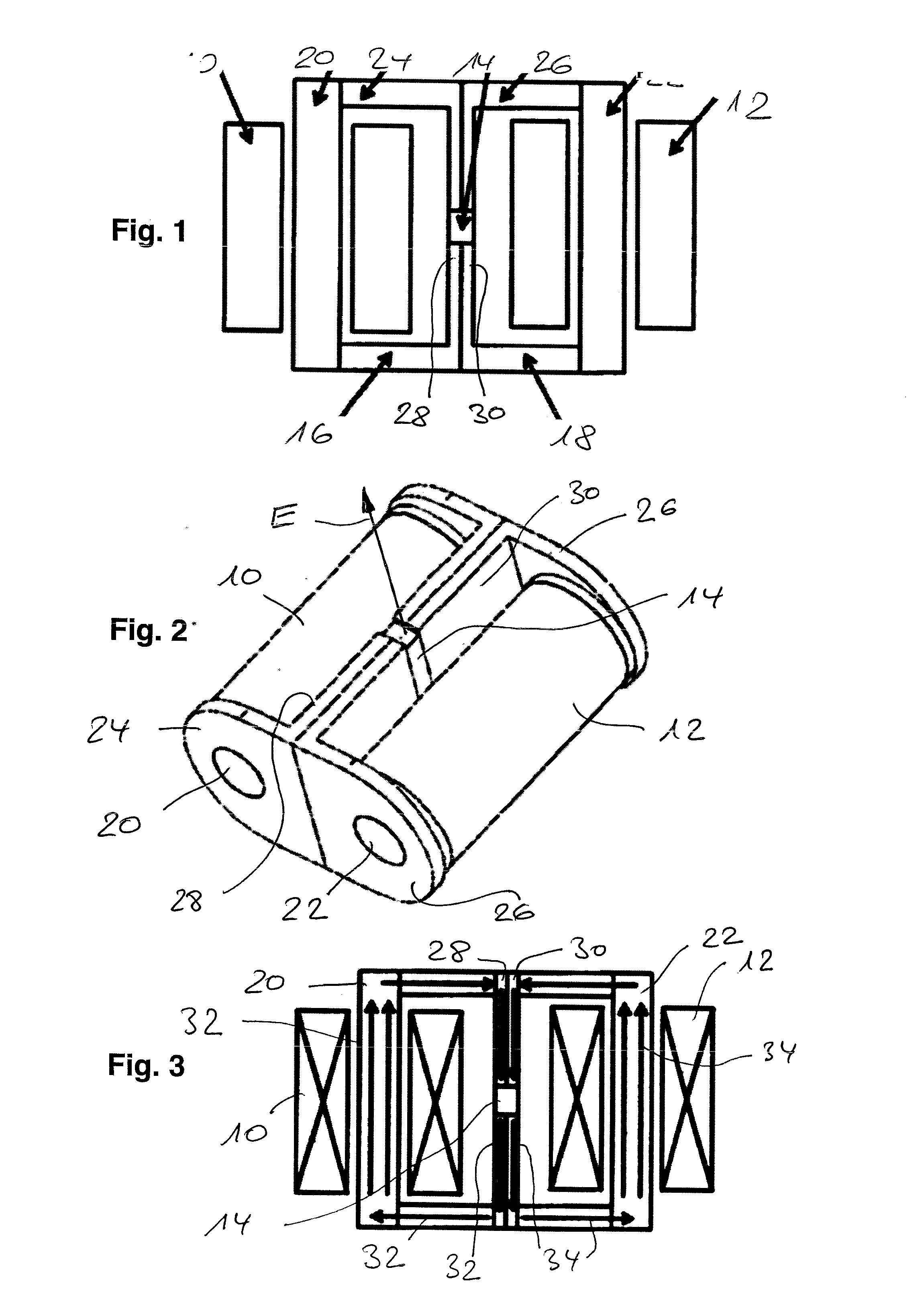
[0030]A first form of embodiment of the invention, represented in FIGS. 1 to 3, has an actuator with two coil devices 10, 12, which are located opposite to each other, with respect to an extended MSM drive element 14 (direction of expansion at right-angles out of the plane of FIG. 1). The magnetic flux-conducting circuits 16, 18 respectively are assigned to the coil devices 10, 12 respectively; the circuits consist of core regions 20, 22 respectively, surrounded by the coils 10, 12, adjacently connecting sections 24, 26 respectively and in each case flux-conducting sections 28, 30 respectively introducing a magnetic flux of the energised coils 10, 12 into the drive element 14.

[0031]In the practical implementation, cf. the perspective view of a possible build in FIG. 2, the flux-conducting sections 28, 30 respectively are designed as flat central sections (more precisely: the respective central core sections of the latter) of a frame arrangement encompassing a coil 10, 12 respectivel...


PUM


Abstract

An actuator having a drive element which is made of a magnetic shape memory material, can be driven in response to electrical control of a plurality of coil apparatuses (10, 12) and is designed to carry out an expansion movement in response to said control, wherein the coil apparatuses are magnetically connected to the drive element (14) via flux-concentrating means (20, 22, 24, 26, 28, 30), and a flux-concentrating section of the flux-concentrating means is associated with the coil apparatuses for interaction with the drive element. The invention provides for the flux-concentrating means for each of the plurality of coil apparatuses to have a core section (20, 22, 30) and a connecting section (24, 26), which conducts a magnetic flux to the drive element, such that a magnetic flux-concentrating circuit for each of the coil apparatuses is formed by the common drive element, wherein the flux-concentrating circuits are magnetically connected in parallel with one another, based on the common drive element, and/or a magnetic flux direction of a magnetic flux in the particular flux-concentrating circuit in the drive element has the same orientation.

Description

BACKGROUND OF THE INVENTION[0001]The present invention concerns an actuator as it is disclosed in WO 99 / 45631.[0002]Electromagnetic actuation devices, in which a shape memory material (shape memory alloy material) experiences an expansion as a reaction to an applied magnetic field and as a result can then interact with an actuation partner to execute an actuation reaction, are of known prior art. Typically a coil device is thereby assigned to the magnetic shape memory material (MSM=“Magnetic Shape Memory”), which as a reaction to an energisation generates the magnetic field required for the expansion of the shape memory drive element. Since in typical drive element configurations, for example, along a designated axis of expansion of extended bodies, for purposes of triggering the expansion movement a magnetic field input must occur in the body orthogonal to the direction of expansion, a compact build shape can be achieved only with difficulty when implementing suitable modular arran...

Claims


Application Information

Patent Timeline
Patent Type & Authority Applications(United States)
IPC IPC(8): H02N2/00
CPCH02N2/005H10N35/00H02N2/00H10N35/85
Inventor SCHIEPP, THOMASLAUFENBERG, MARKUS
Owner ETO MAGNETIC GMBH
Why Eureka
Try Eureka