Implantable microphone for hearing systems

a technology of implantable microphones and hearing systems, applied in the direction of electrical equipment, deaf-aid sets, etc., can solve the problems of affecting the hearing of the affected and surrounding tissue, the natural ability of the outer ear of directionally filtering the received sound is lost, and the power consumption of such electromagnetic and electrodynamic converters is relatively high, and limits the practical application of cochlear implants and other implantable hearing systems

Active Publication Date: 2014-04-10
MED EL ELEKTROMEDIZINISCHE GERAETE GMBH
View PDF4 Cites 8 Cited by
  • Summary
  • Abstract
  • Description
  • Claims
  • Application Information

AI Technical Summary

Benefits of technology

[0013]In some embodiments, the vibration sensor may be coupled to the sidewall and / or coupled to the second membrane. The vibration sensor may be a piezoelectric sensor and / or may be a MEMS differential capacitor. The piezoelectric sensor may be shaped as a rectangular bar. The opening may be in the sidewall. When the opening is in the sidewall, the fluid may be permitted to flow from the first volume to the second volume and / or to an area external to the housing. The second volume may include a second opening in a back wall and / or the sidewall. The fluid may be a gas and / or a liquid. The vibration sensor may be coupled to the second membrane with a coupling element positioned between the vibration sensor and the second membrane and configured to move the vibration sensor in response to movement from the second membrane. The housing may further include a back wall adjacent to the sidewall and having a recess configured to be coupled to the auditory ossicle. The recess may include a channel extending to the sidewall. The recess may be substantially aligned with a center of the first membrane. The implantable microphone may further include a spring element coupled to the vibration sensor and configured to contact a back wall of the housing. The implantable microphone may further include one or more additional vibration sensors adjacent to the vibration sensor and coupled to the sidewall and / or the vibration sensor. The implantable microphone may further include a spring element coupled to the one or more additional vibration sensors and configured to contact the housing and to assist in keeping the one or more vibration sensors in contact with each other and the second membrane. The vibration sensor may include a stack of vibration sensors. The first volume may be less than the second volume.

Problems solved by technology

However, with this approach, the natural ability of the outer ear of directionally filtering the received sound is lost and / or the attachment of the required converter components can cause adverse reactions of the affected and surrounding tissue.
However, the relatively high power consumption of such electromagnetic and electrodynamic converters limits their practical application for cochlear implants and other implantable hearing systems.
This disadvantage is obviated by converters based on piezoelectric principles.
The problem with this approach is that inflexible connections to the ear ossicles can cause bone erosion, so that cementing converter components in the middle ear space is approached cautiously for mechanical and toxicological reasons.
Moreover, the patent reference does not indicate how the body fluids can be permanently prevented from making contact with the piezoelectric materials.
Accordingly, there is a risk of biocompatibility problems, so that the piezoelectric properties can deteriorate due to physical and chemical interactions between the piezoelectric material and the body fluids.
However, the attachment of the converter to an oscillating middle ear component, such as the ear drum or the ear ossicles, is either not permanently stable or can erode the bone.
This risk is aggravated because the mass of the implantable converter is greater than that of passive middle ear implants.
Since the stapes in conjunction with the coupled inner ear forms a resonant system, it may not have sufficient sensitivity across the entire range of useful frequencies.

Method used


Image

  • Implantable microphone for hearing systems
  • Implantable microphone for hearing systems
  • Implantable microphone for hearing systems

Examples


Embodiment Construction

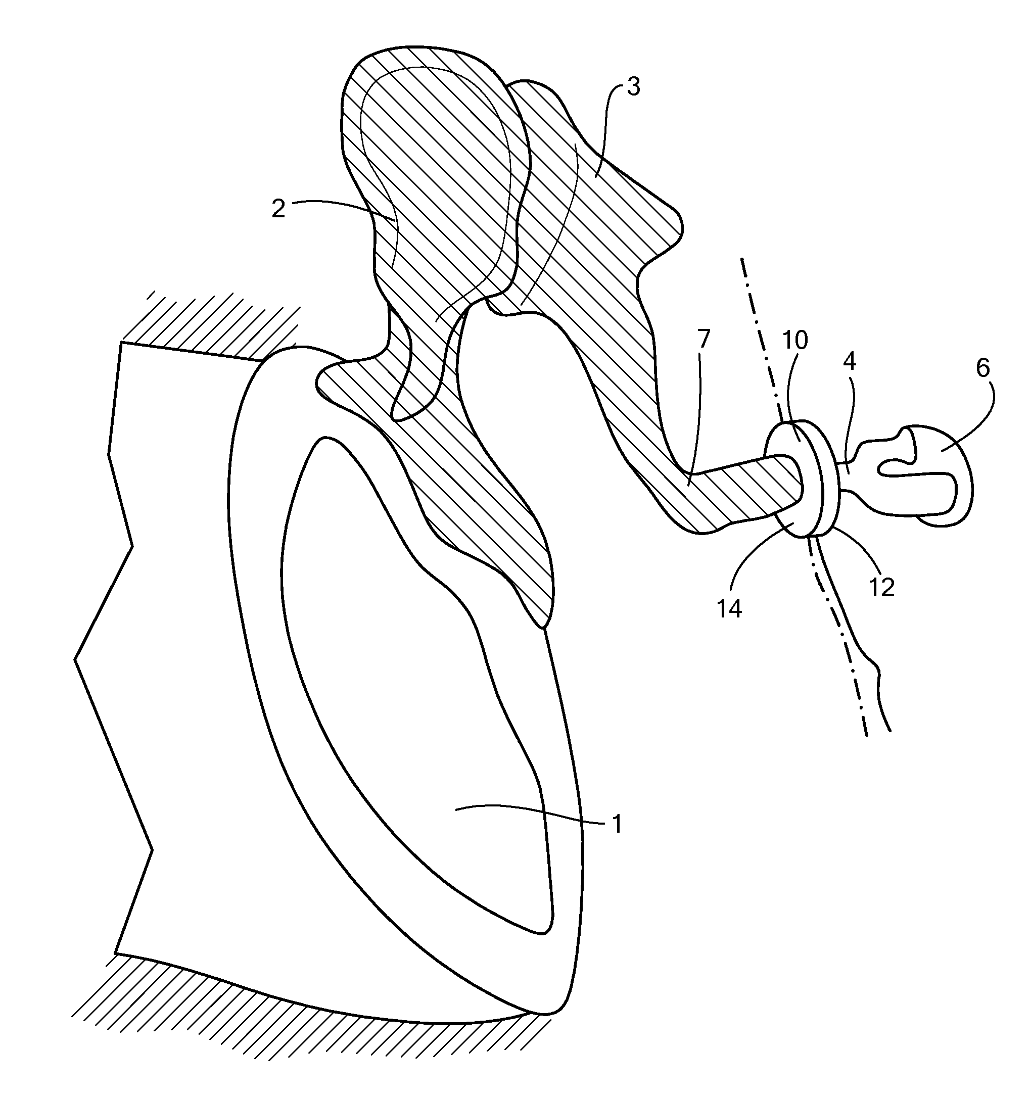
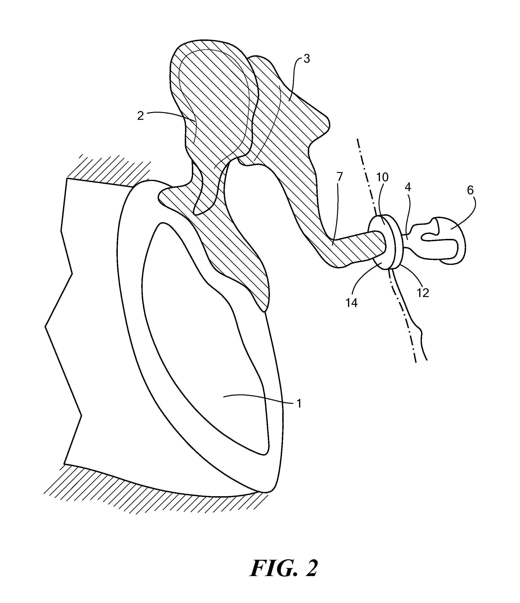
[0012]In accordance with one embodiment of the invention, an implantable microphone for use in hearing systems includes a housing having a sidewall, a first membrane coupled to a top portion of the housing and configured to move in response to movement from an auditory ossicle, and a second membrane coupled to the sidewall such that an interior volume of the housing is divided into a first volume and a second volume. The first volume has an opening that permits fluid to flow from the first volume. The implantable microphone also includes a vibration sensor coupled to the second membrane and configured to measure the movement of the second membrane and to convert the measurement into an electrical signal.

[0013]In some embodiments, the vibration sensor may be coupled to the sidewall and / or coupled to the second membrane. The vibration sensor may be a piezoelectric sensor and / or may be a MEMS differential capacitor. The piezoelectric sensor may be shaped as a rectangular bar. The openi...


PUM


Abstract

An implantable microphone for use in hearing systems includes a housing having a sidewall, a first membrane coupled to a top portion of the housing and configured to move in response to movement from an auditory ossicle, and a second membrane coupled to the sidewall such that an interior volume of the housing is divided into a first volume and a second volume. The first volume has an opening that permits fluid to flow out from the first volume. The implantable microphone also includes a vibration sensor coupled to the second membrane and configured to measure the movement of the second membrane and to convert the measurement into an electrical signal. The vibration sensor may include a piezoelectric sensor and/or a MEMS sensor.

Description

CROSS-REFERENCE TO RELATED APPLICATIONS[0001]This patent application is a continuation-in-part of U.S. patent application Ser. No. 12 / 952,934 filed Nov. 23, 2010, which claims the benefit of U.S. Provisional Patent Application No. 61 / 264,139 filed Nov. 24, 2009, the disclosures of which are incorporated by reference herein in its entirety.TECHNICAL FIELD[0002]The present invention relates to implantable microphones, and more specifically to implantable microphones with vibration sensors, also regarded as force sensor, for use with cochlear implants and other hearing systems.BACKGROUND ART[0003]Implantable microphones for use with cochlear implants and other hearing systems typically require an implantable converter for receiving the sound reaching the ear of the patient and converting the sound into electrical signals for further processing in the hearing system. Different solutions have been proposed in the past. In one approach, the sound waves reaching the ear are directly conver...

Claims


Application Information

Patent Timeline
Patent Type & Authority Applications(United States)
IPC IPC(8): H04R25/00
CPCH04R25/606
Inventor HELLMUTH, ALEXANDERZAHNERT, THOMASHOFMANN, GERTBORNITZ, MATTHIASSEIDLER, HANNESHUTTENBRINK, KARL-BERND
Owner MED EL ELEKTROMEDIZINISCHE GERAETE GMBH
Why Eureka
Try Eureka