

MEMS sensor, method of manufacturing thereof, and electronic apparatus
a sensor and micro-electromagnetic system technology, applied in the direction of acceleration measurement in multiple dimensions, turn-sensitive devices, instruments, etc., can solve the problems of poor sensitivity, increase brownian noise, reduce the mass of the movable portion, etc., and achieve the effect of improving detection accuracy
- Summary
- Abstract
- Description
- Claims
- Application Information
AI Technical Summary
Benefits of technology
Problems solved by technology
Method used
Image

Examples
first embodiment
1. First Embodiment
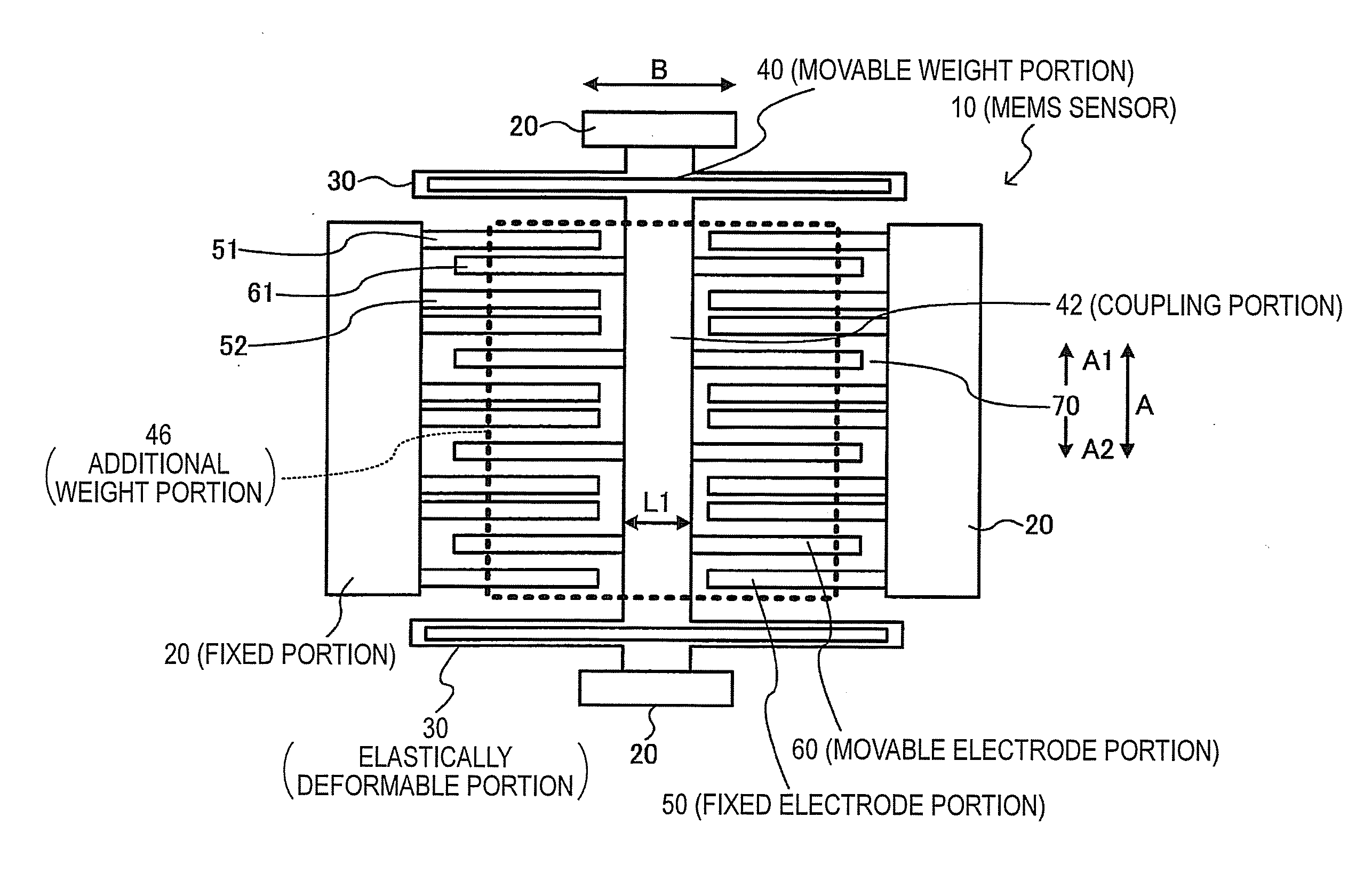
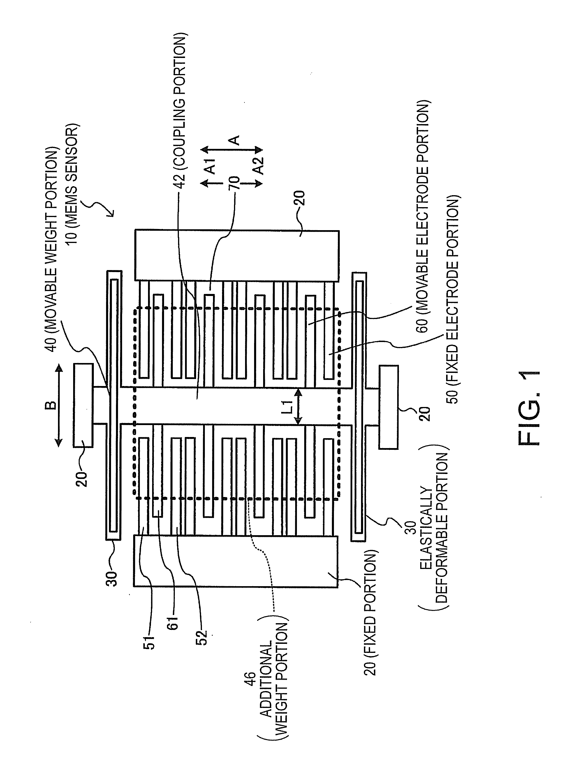
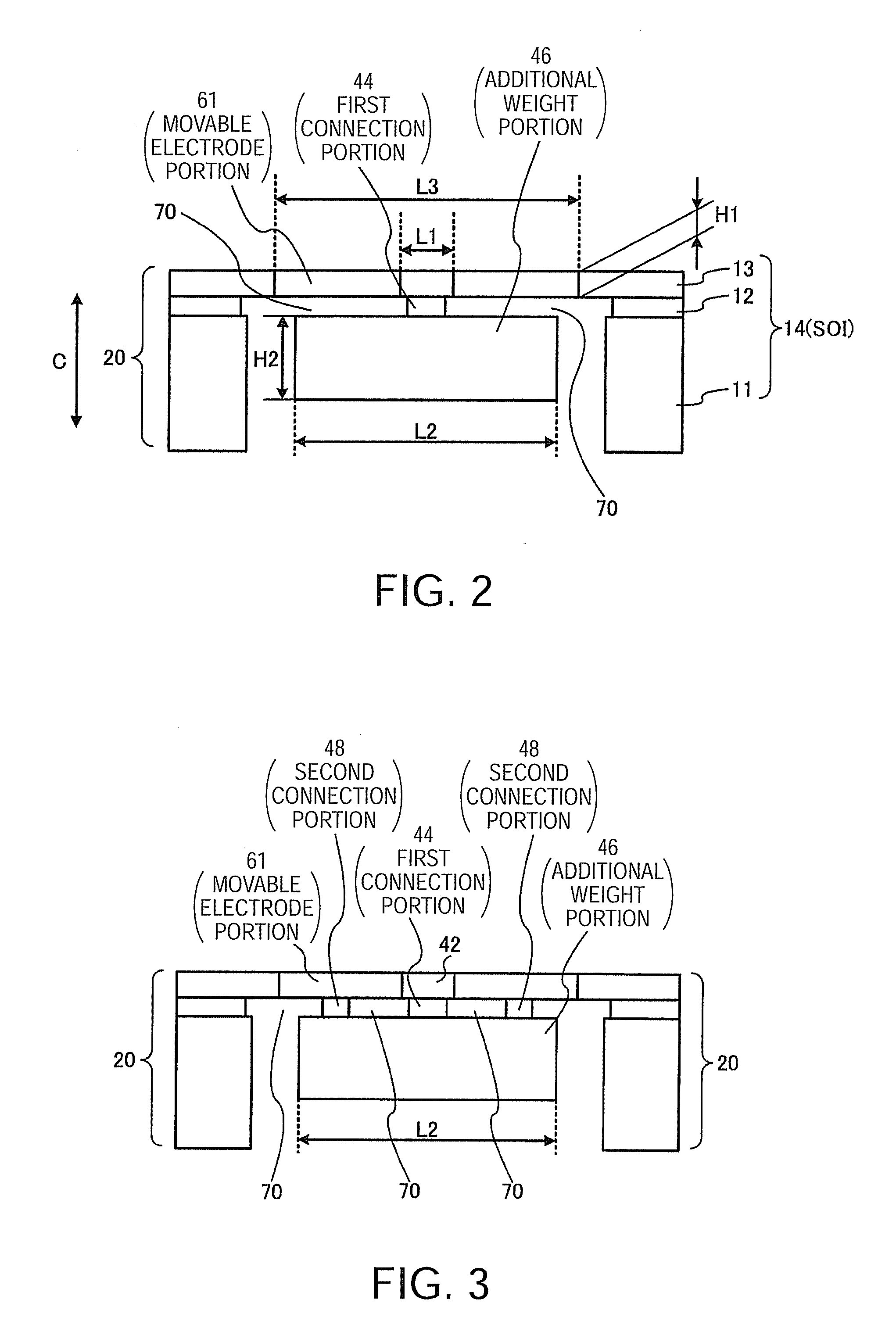
[0044]FIG. 1 is a plan view showing an exemplary structure of a MEMS sensor (electrostatic capacitive MEMS acceleration sensor in this case) according to a first embodiment of the invention. FIG. 2 is a longitudinal sectional view of the MEMS sensor including movable electrode portions in FIG. 1.
Overall Configuration
[0045]In the following description, although an SOI (Silicon On Insulator) substrate 14, for example, can be used for a supporting substrate 11, an intermediate layer 12, and a functional layer 13 as the basic stacked structure of the MEMS sensor 10 shown in FIG. 2, this is not restrictive. The embodiment uses the SOI substrate 14 in which the supporting substrate 11 is silicon; the intermediate layer 12 is SiO2; and the functional layer 13 is silicon as an active layer of the SOI substrate 14. In the embodiment, the functional layer 13 is doped with an impurity, so that a conductivity function as a fixed electrode or a movable electrode is assured. Re...
second embodiment
2. Second Embodiment
[0083]FIG. 10 is a plan view of a two-axis acceleration sensor (MEMS sensor) 300 according to a second embodiment of the invention. As shown in FIG. 10, the MEMS sensor 300 can have fixed portions 320, elastically deformable portions 330, a movable weight portion 340, fixed electrode portions 350, and movable electrode portions 360. The fixed portion 320 can be formed in a frame shape so as to surround the elastically deformable portions 330, the movable weight portion 340, the fixed electrode portions 350, and the movable electrode portions 360 from all four sides. The movable weight portion 340 is coupled to the fixed portions 320 via the elastically deformable portions 330, and has hollow portions 370 formed therearound.
[0084]The fixed electrode portion 350 has first fixed electrode portions 350A secured to the fixed portion 320 to be arranged along the first direction A and protruding along the second direction B perpendicular to the first direction A. The fi...
third embodiment
3. Third Embodiment
[0088]FIG. 11 is a plan view of a gyro sensor 400 according to a third embodiment of the invention. The gyro sensor 400 has the same structure as that of the two-axis acceleration sensor 300 shown in FIG. 10. Therefore, the same reference numerals and signs as those in FIG. 10 are assigned to the constituents of the gyro sensor 400, and the detailed description thereof is omitted. However, the gyro sensor 400 is different in detection principle from the two-axis acceleration sensor 300 shown in FIG. 10.
[0089]The gyro sensor 400 causes the Coulomb force to act between the second fixed electrode portion 350B and the second movable electrode portion 360B, thereby vibrating the movable weight portion 340 in the second direction B at a constant rate. In this sense, the second fixed electrode portion 350B and the second movable electrode portion 360B constitute a drive electrode.
[0090]In a state where the movable weight portion 340 vibrates in the second direction B at ...
PUM
| Property | Measurement | Unit |
|---|---|---|
| weight | aaaaa | aaaaa |
| width | aaaaa | aaaaa |
| length | aaaaa | aaaaa |
Abstract
Description
Claims
Application Information