High efficiency, smooth robot design

a robot design and high efficiency technology, applied in the field of underwater robots, can solve the problems of few propulsive systems and challenging requirements

Inactive Publication Date: 2014-04-17
MASSACHUSETTS INST OF TECH
View PDF8 Cites 15 Cited by
  • Summary
  • Abstract
  • Description
  • Claims
  • Application Information

AI Technical Summary

Benefits of technology

[0008]In a specific implementation, an underwater robot includes a body having a first end and a second end, a propeller coupled to the first end of the body, a controller having a processor for receiving sensor information and for causing control signals to be generated, and first and second actuation units responsive to the controller processor control signals, where the first and second actuation units are positioned inside the body, and each actuation unit includes a pump and two valves coupled to the pump. As the propeller propels the robot, the controller causes jets of fluid outputted from the first and second actuation units to stabilize the movement of the robot.

Problems solved by technology

These requirements are challenging because few propulsive systems can be designed to fit into a smooth, streamlined body.

Method used


Image

  • High efficiency, smooth robot design
  • High efficiency, smooth robot design
  • High efficiency, smooth robot design

Examples


Embodiment Construction

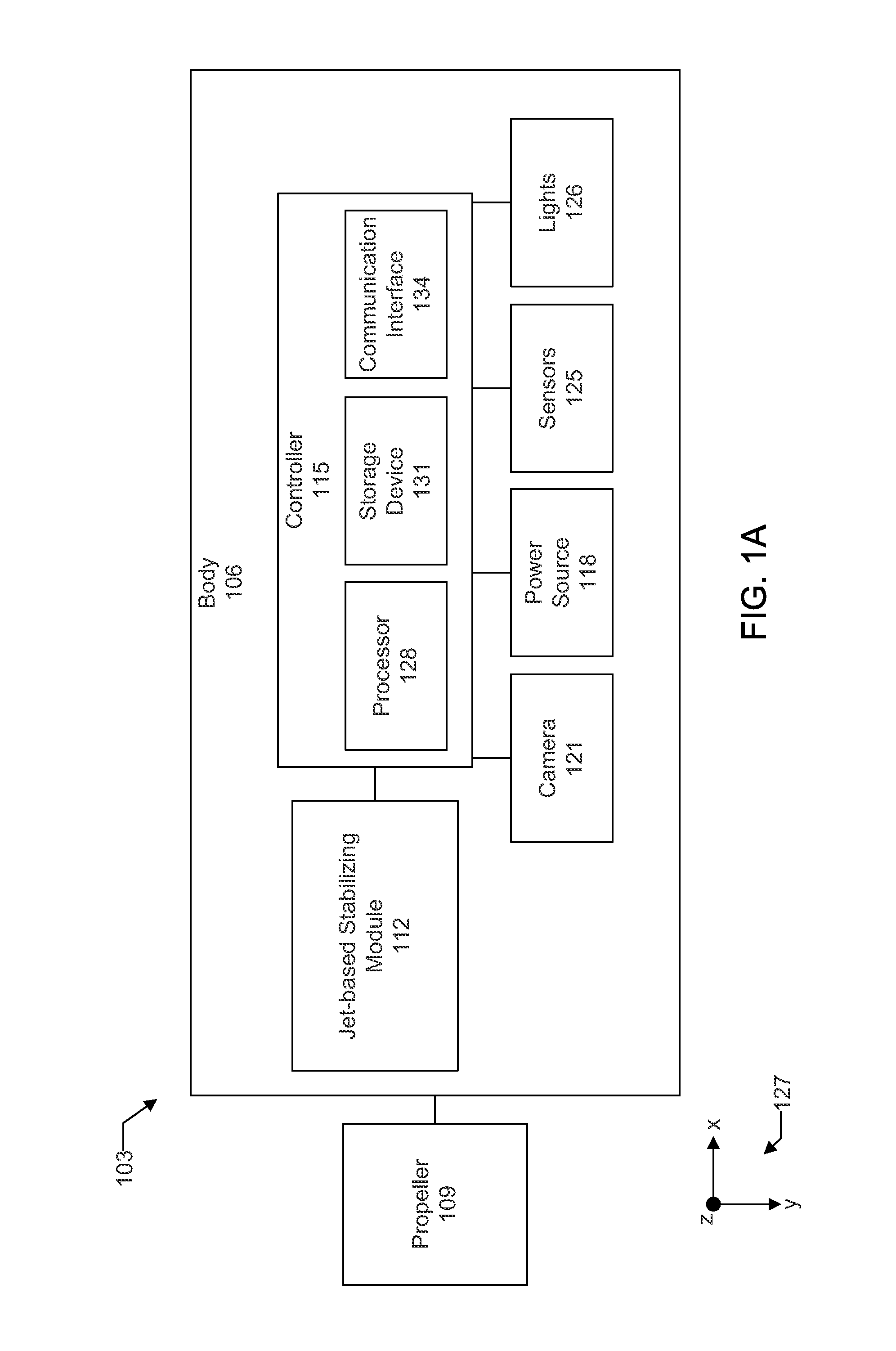
[0061]FIG. 1A shows a block diagram of a first embodiment of an underwater vehicle 103. This vehicle includes a body 106 and propeller 109 connected to an end of the body. Positioned inside the body are a jet-based stabilizing module 112 and a controller 115. The controller may be connected to the stabilizing module, a power source 118, a camera 121, a sensor 125, and lighting 126. A set of Cartesian coordinate system axes 127 are shown with the figure to help indicate orientation. There is an x-axis, y-axis, and z-axis. The x and y axes are perpendicular to each other and lie in a first plane. The z-axis lies in a second plane, perpendicular to the first plane.

[0062]The controller may include a processor 128, storage device 131, and a communications interface 134. The processor may be referred to as a central processing unit (CPU). The processor may include multiple processors or a multicore processor, which may permit parallel processing of information. The storage device may incl...


PUM


Abstract

An underwater robot includes a body, a propeller connected to an end of the body, a controller, and first and second actuation units that output jets of fluid. The propeller propels the robot, and the controller stabilizes the robot using the jets of fluid. The controller determines which actuation unit to activate based on a calculation involving a yaw rate and a yaw angle of the robot.

Description

CROSS-REFERENCE TO RELATED APPLICATIONS[0001]This patent application claims priority to U.S. provisional patent application 61 / 714,290, filed Oct. 16, 2012, which is incorporated by reference along with all other references cited in this application.TECHNICAL FIELD[0002]The present invention relates to the field of underwater vehicles, including, more particularly, to underwater robots.BACKGROUND OF THE INVENTION[0003]There is a continuing demand for underwater robots that can access confined spaces and efficiently move through the water. For example, to access complex underwater structures, it is desirable that robots be tetherless, compact, highly maneuverable, and have a smooth body shape with minimal appendages. These requirements are challenging because few propulsive systems can be designed to fit into a smooth, streamlined body. A moment referred to as the “Munk moment” is destabilizing for elongated bodies. For example, the moment tends to rotate them broadside to the flow.[...

Claims


Application Information

Patent Timeline
Patent Type & Authority Applications(United States)
IPC IPC(8): B25J9/16
CPCB25J9/1651G05D1/0875B63G8/16B63G2008/002G21C17/013
Inventor ASADA, HARUHIKO HARRYMAZUMDAR, ANIRBANLOZANO, MARTINFITTERY, AARON MICHAEL
Owner MASSACHUSETTS INST OF TECH
Why Eureka
Try Eureka