

Heating element and method for manufacturing same
a technology of heating element and manufacturing method, which is applied in the direction of resistive material coating, vehicle maintenance, vehicle cleaning, etc., can solve the problems of condensation, difficult to drive the heating glass manufactured by the method at low voltage, and condensation on the windows of the vehicl
- Summary
- Abstract
- Description
- Claims
- Application Information
AI Technical Summary
Benefits of technology
Problems solved by technology
Method used
Image

Examples
example
Example 1
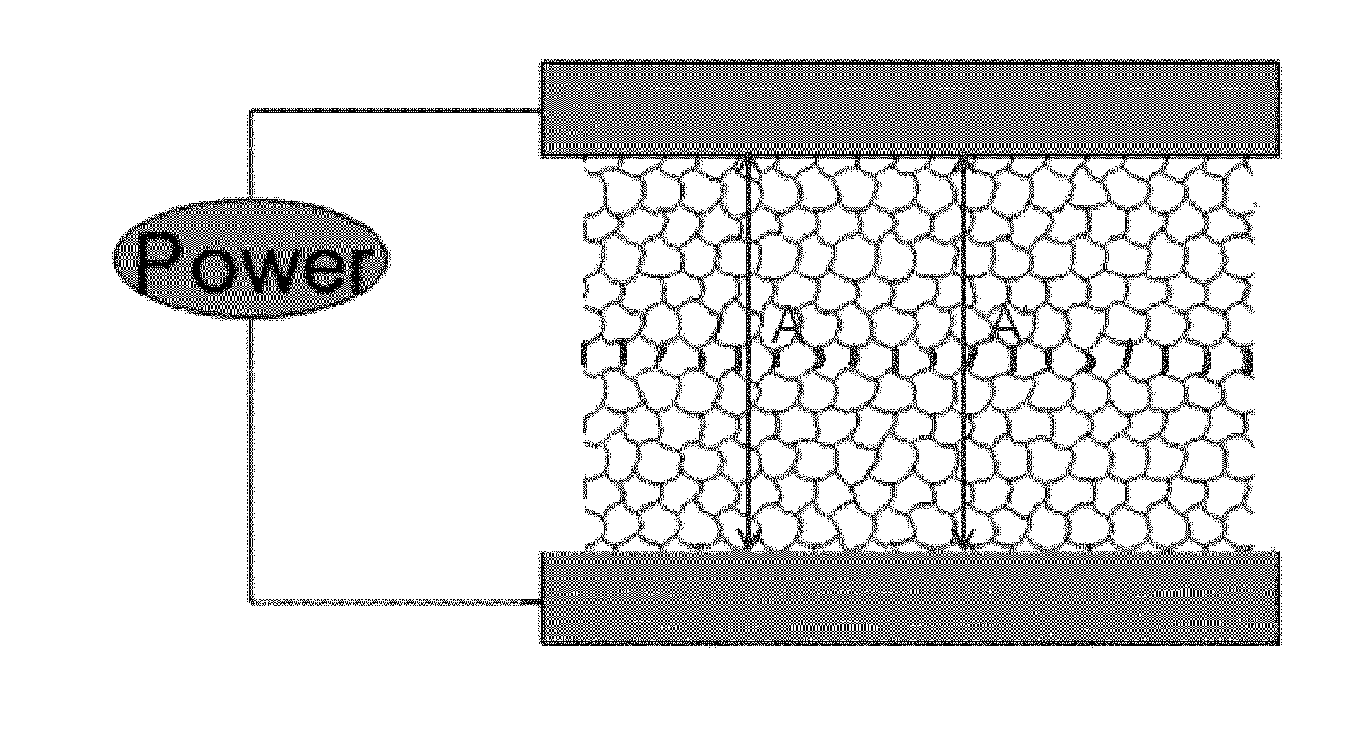
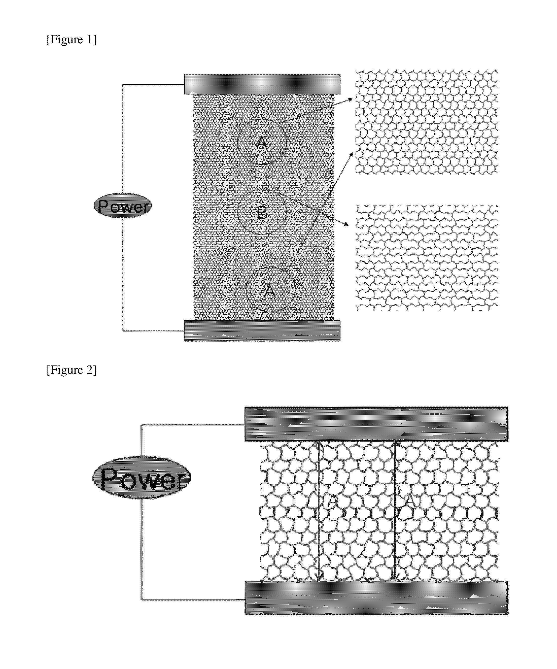
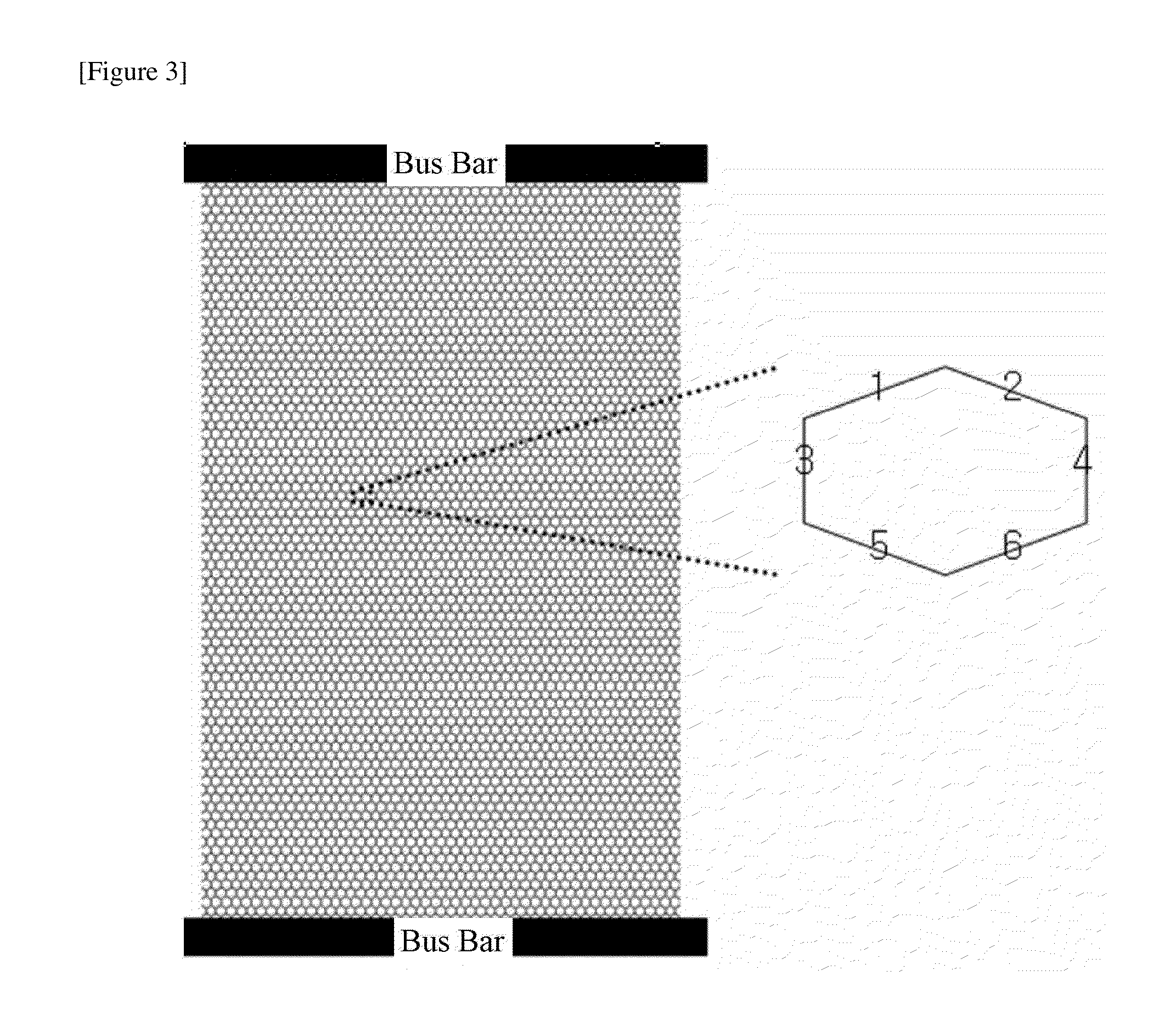
[0096]A Cu layer having a thickness of 2 μm was formed on a polyurethane terephthalate (PET) film through a vapor deposition method. After an etching resist material was patterned on the film through a photolitho process, a conductive heating pattern region comprising a metal pattern having a line width from 5 μm to 8 μm and a line height of 2 μm was formed through an etching process. The conductive heating pattern had an a value of 155 μm as illustrated in FIG. 7 and was formed at 20 cm wide and 15 cm long and 5 cm per region as illustrated in FIG. 5, and then was formed to have 20×10 cm2 for each region by being extended by two times longitudinally as illustrated in FIG. 11. Bus bars were respectively provided on and under the conductive heating pattern, and as illustrated in FIG. 1, a pattern having the number of lines of 2:1:2 for each region according to the distance from the bus bar was formed. When 5 V was applied to the bus bars, a current of 4.6 A flowed. 10 minute...
example 2
[0097]A conductive film was formed in the same manner as in Example 1. In Example 2, a value was fixed to 158 μm, and as illustrated in FIG. 5, a pattern with the number of lines for each region of 4:3:4 was formed according to the distance from the bus bar. When 5 V was applied to the bus bars, a current of 6.0 A flowed. 10 minutes before and after the voltage was applied thereto, the temperature difference of the film was measured using a thermal imaging camera (FLIR), and as a result, the temperature was increased by 21.3° C., 28.1° C., and 19.1° C. for each region. Since the increased temperature is proportional to the heating value, it can be seen that a heating value of 3:4.0:2.7, which is nearly inversely proportional to the ratio of the numbers of lines (4:3:4) according to the distance from the bus bar, was exhibited. In this case, when the transmittance for each region was measured, 89.2%, 90.1%, and 89.6% were obtained.
example 3
[0098]A conductive film was formed in the same manner as in Example 1. In Example 3, a value was fixed to 135 μm, and as illustrated in FIG. 6, a pattern with the numbers of lines for each region of 20:12:15 according to the distance from the bus bar was formed. When 5 V was applied to the bus bars, a current of 5.4 A flowed. 10 minutes before and after the voltage was applied thereto, the temperature difference of the film was measured using a thermal imaging camera (FLIR), and as a result, the temperature was increased by 15.8° C., 28.3° C., and 19.0° C. for each region. Since the increased temperature is proportional to the heating value, it can be seen that a heating value of 12:21:14, which is nearly inversely proportional (12:20:16) to the ratio of the numbers of lines (20:12:15) according to the distance from the bus bar, was exhibited. In this case, when the transmittance for each region was measured, 88.4%, 89.8%, and 89.2% were obtained.
PUM
| Property | Measurement | Unit |
|---|---|---|
| Fraction | aaaaa | aaaaa |
| Fraction | aaaaa | aaaaa |
| Diameter | aaaaa | aaaaa |
Abstract
Description
Claims
Application Information