Manipulator system

a manipulator and system technology, applied in the field of manipulators, can solve problems such as the inability of the slave manipulator to work

Active Publication Date: 2014-05-01
OLYMPUS CORP
View PDF26 Cites 40 Cited by
  • Summary
  • Abstract
  • Description
  • Claims
  • Application Information

AI Technical Summary

Benefits of technology

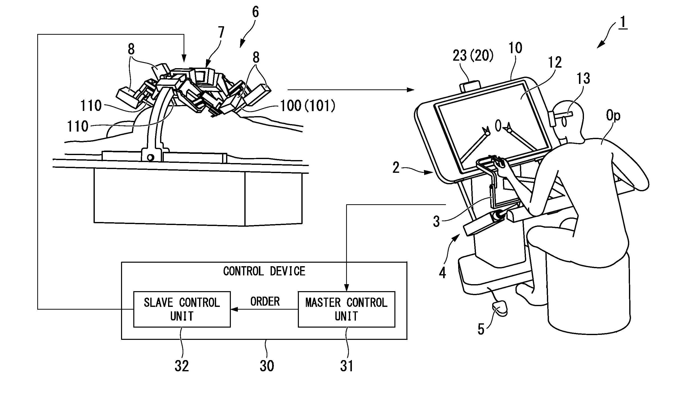
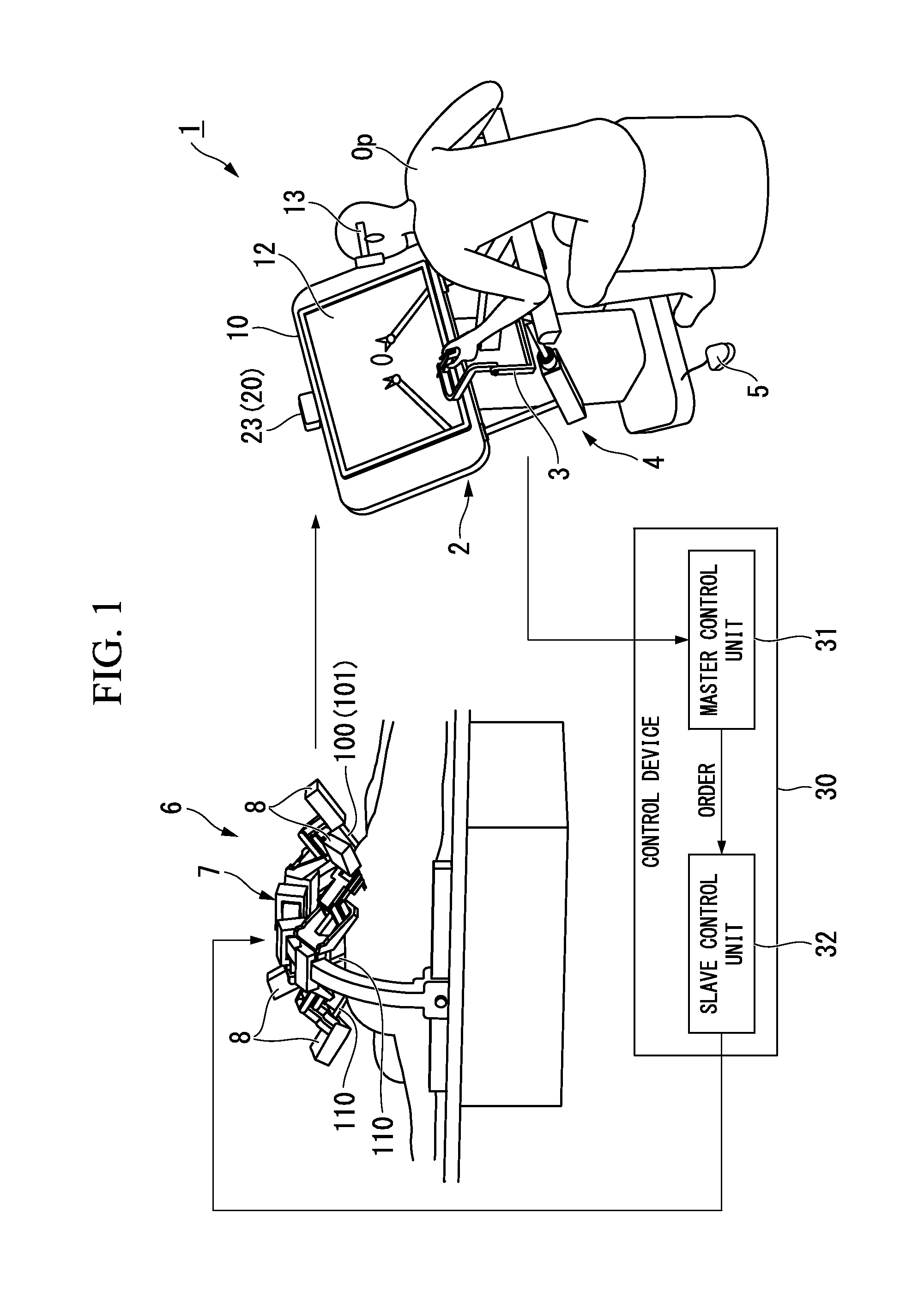
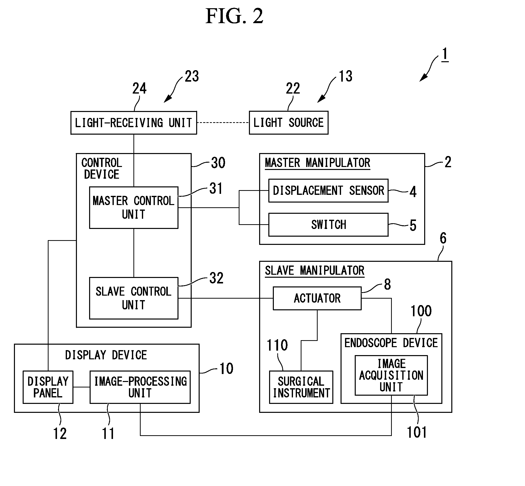
[0007]According to a first aspect of the present invention, a manipulator system includes a master manipulator configured to send an input command based on manipulation by an operator; a slave manipulator configured to operate in accordance with the input command; an image capturing unit configured to acquire an image of an object; a display device placed in front of the operator and configured to display the image acquired by the image capturing unit; a detection device configured to detect a direction of an operator's face with respect to the display device; and a control unit configured to determine whether the direction of the operator's face is within a predetermined angle with respect to the display device based on a detection result in the detection device, and to shift an operation mode of the slave manipulator between a predetermined first control mode and a second control mode in which an operation is limited more than in the first control mode based on a determination result.

Problems solved by technology

According to the manipulator control system, even though the master manipulator is operated when the operator does not see an object to be treated, the slave manipulator does not work.

Method used


Image

  • Manipulator system
  • Manipulator system
  • Manipulator system

Examples


first modified example

[0120]Next, a first modified example of the above-mentioned first embodiment will be described. FIG. 8 is a schematic view showing a detection device of the modified example.

[0121]As shown in FIG. 8, the modified example is different from the first embodiment in that the detection device 20 is replaced with a detection device 20A.

[0122]The detection device 20A includes a plurality of light sources 22A configured to emit light having high directionality, and the light-receiving unit 24 described in the first embodiment.

[0123]In the plurality of light sources 22A, optical axes are directed toward an upper end, a center, and a lower end of the vertical irradiation angle in the index unit 21, respectively.

[0124]Even in the configuration shown in the modified example, the same effect as the first embodiment is obtained.

[0125]In addition, in the modified example, a light source 22A1, a light source 22A2, and a light source 22A3 having different wavelengths or intensities of the emitted li...

second modified example

[0127]Next, a second modified example of the above-mentioned first embodiment will be described. FIG. 9 is a schematic view showing a detection device of the modified example.

[0128]As shown in FIG. 9, the modified example is different from the first embodiment in that the detection device 20 is replaced with a detection device 20B.

[0129]In the detection device 20B, instead of the light-receiving unit 24, a light-receiving unit 24B having a light-receiving surface 25B at which a plurality of light-receiving elements are arranged is installed.

[0130]In the modified example, as it is detected to which one of the plurality of light-receiving elements the light emitted from the light source 22 is irradiated, a direction to which the light source 22 is moved with respect to the light-receiving unit 24B can be detected.

third modified example

[0131]Next, a third modified example of the above-mentioned first embodiment will be described. FIG. 10 is a perspective view showing a partial configuration of a manipulator system of the modified example.

[0132]The modified example is different from the first embodiment in that the detection device 20B described in the above-mentioned second modified example is provided, and the master control unit 31 is differently operated from the above-mentioned first embodiment.

[0133]In addition, the third modified example is different from the first embodiment in treatment of the master control unit 31 in step S107. That is, when it is determined that the direction of the face of the operator Op does not face the display panel 12 in step S106 of the first embodiment, the master control unit 31 displays arrow symbols (see reference numeral Q1 of FIG. 10) of a direction which is an opposite direction of the light source 22 being moved with respect to the light receiving unit 24 upon determinati...


PUM


Abstract

A manipulator system includes a master manipulator configured to send an input command, a slave manipulator configured to operate according to the input command, an image capturing unit configured to acquire an image of an object, a display device placed in front of the operator and configured to display the image acquired by the image capturing unit, a detection device configured to detect the direction of an operator's face of the operator with respect to the display device, and a control unit configured to determine whether the direction of the operator's face is within a predetermined angle with respect to the display device based on the detection result in the detection device, and to shift an operation mode of the slave manipulator between a first control mode and a second control mode in which an operation is limited more than in the first control mode based on a determination result.

Description

BACKGROUND OF THE INVENTION[0001]1. Field of the Invention[0002]The present invention relates to a manipulator system. This application is a continuation application based on PCT Patent Application No. PCT / JP2012 / 068252, filed Jul. 11, 2012, claiming priority based on Japanese Patent Application No. 2011-156778 filed on Jul. 15, 2011. The contents of both the PCT Patent Application and the Japanese Patent Application are incorporated herein by reference.[0003]2. Description of Related Art[0004]In the conventional art, as an operation support system, a manipulator system including a master manipulator operated by an operator, and a slave manipulator configured to perform processing based on an operation of the master manipulator is known.[0005]For example, Japanese Unexamined Patent Application, First Publication No. H7-124165 discloses a manipulator control system including a master manipulator (a master arm), a slave manipulator, a stereoscopic scope installed at the slave manipula...

Claims


Application Information

Patent Timeline
Patent Type & Authority Applications(United States)
IPC IPC(8): A61B19/00B25J3/00
CPCA61B19/2203B25J3/00B25J3/04B25J9/1689A61B2090/502A61B2090/368A61B34/30A61B34/37A61B2090/371A61B2090/372
Inventor OGAWA, RYOHEIKISHI, KOSUKE
Owner OLYMPUS CORP
Why Eureka
Try Eureka