Automatic locking slider for slide fastener

Inactive Publication Date: 2014-05-08
JUNG JI ONG
View PDF16 Cites 5 Cited by
  • Summary
  • Abstract
  • Description
  • Claims
  • Application Information

AI Technical Summary

Benefits of technology

[0007]According to the present invention, besides the support groove 2a, the auxiliary support groove 2b is further formed at the bottom of the locking lever accommodation groove 2, and besides the support protrusion 3a, the auxiliary support protrusion 3f is further formed at the locking lever 3. With this, when the locking lever is inserted into the locking lever accommodation groove, the support protrusion 3a of the locking lever is inserted into the support groove 2a, and the auxiliary support protrusion 3f is inserted into the auxiliary support groove 2b. When the locking lever 3 is inserted into the locking lever accommodation groove, the insertion can be performed without any movements in all directions, so the front end of the locking lever can ascend and descend stable along the support groove 2a. In addition, at the top of the support protrusion 3a of the locking lever is formed the upper end surface 3d whose outer side is higher and whose inner side is lower. The lower end 5a′ of the downwardly bent piece 5a extending in the direction of the accommodation groove from one side of the cover 5 comes into contact, so with this it is possible to prevent the support protrusion from being lifted up in the support groove when the front end of the locking lever ascends. Therefore, the support protrusion 3a of the locking lever can be stably supported in the support groove 2a, so the upward and downward movements can be stable in place without using an additional support shaft. The plate spring 5b is formed at the bottom of the cover 5, so when it comes into contact with the top of the plate spring contact part 3e of the upper surface of the locking lever, the pressurization is performed so that the elastic force is transferred to the locking protrusion, whereby the front end of the locking lever can always keep the elastic force in the direction of the locking protrusion. As the locking protrusion 3b of the front end of the locking lever is inserted into between the fasteners, the elastic force can be maintained, and then the slider can be locked.
[0008]When the coil spring 6 is disposed at the bottom of the cover 5, the coil spring is disposed betwe

Problems solved by technology

In the above mentioned conventional art construction, the locking lever does not have a stable operation because the locking lever accommodation groove in which to accommodate the locking lever and the support protrusion and the support groove of the locking lever do not fit precisely, and the construction of the locking lever installed on the inner

Method used


Image

  • Automatic locking slider for slide fastener
  • Automatic locking slider for slide fastener
  • Automatic locking slider for slide fastener

Examples


Example

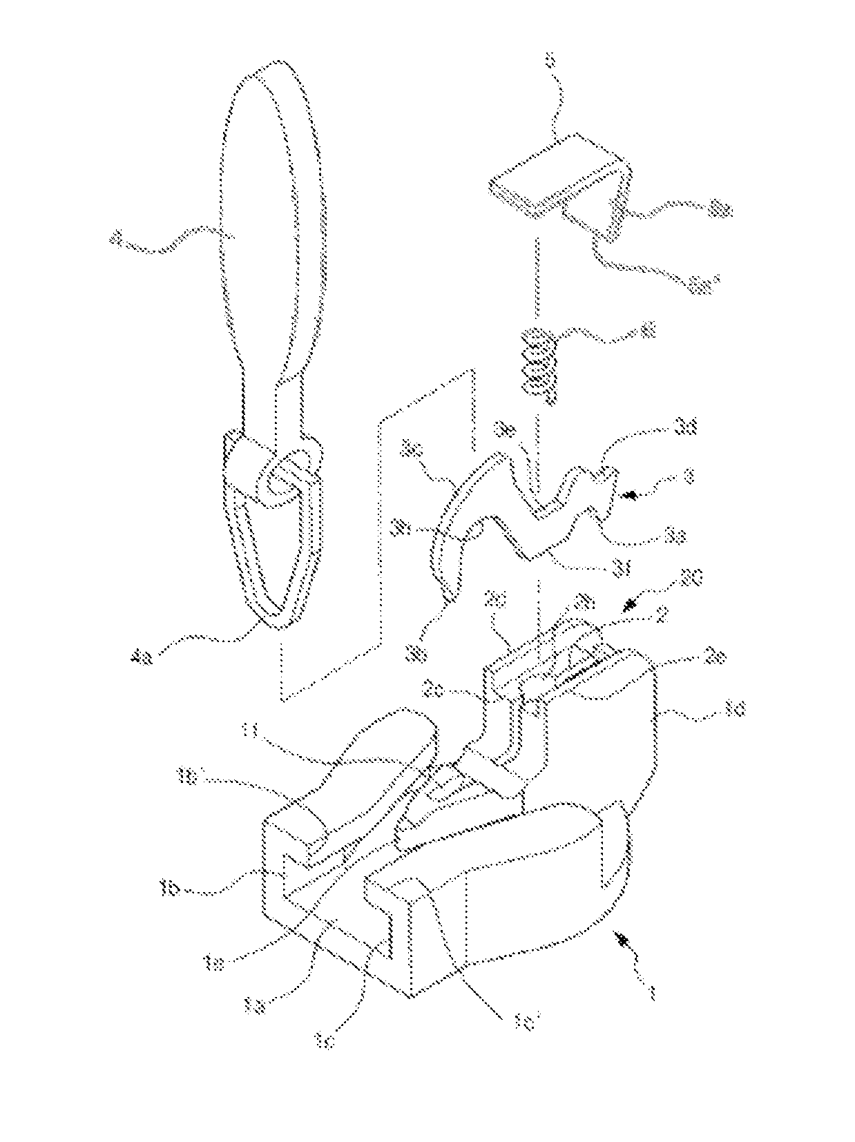
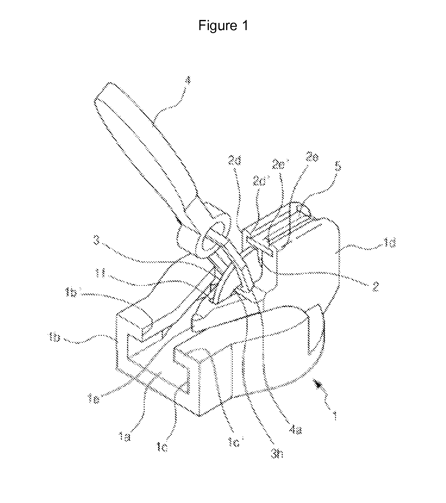
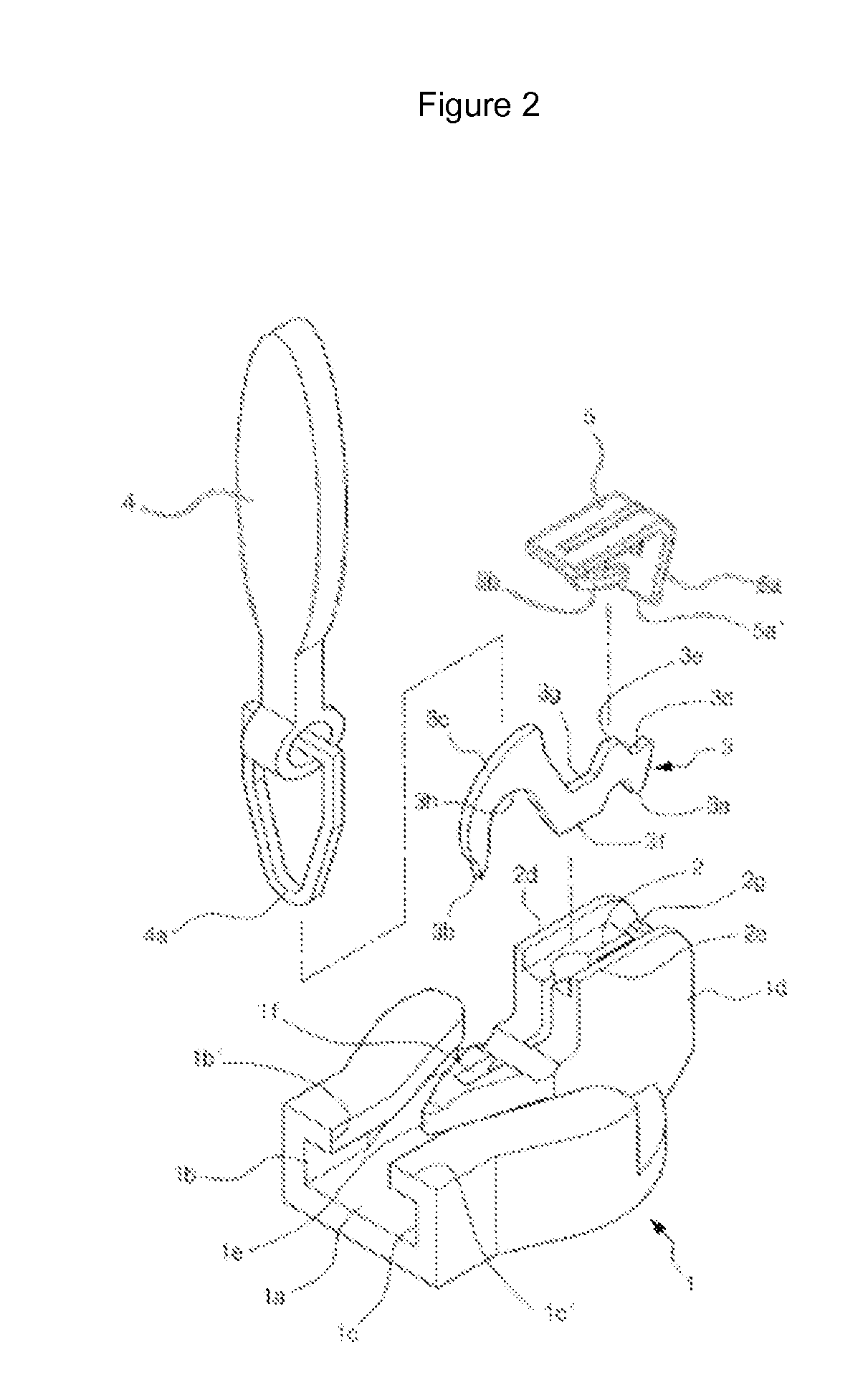
[0019]The preferred embodiments of the present invention will be described. There is provided an automatic locking slider for a slide fastener which has features in that side walls 1b and 1c are formed at the heights corresponding to the height of a fastener in an upward direction from an outer surface of the bottom plate so that a Y-shaped fastener engaging groove is formed on an upper surface of a bottom plate 1a of a slider body, and inward wings 1b′ and 1c′ are formed facing each other in inward directions at the tops of the side walls, and a fastener engaging groove is formed so that the fasteners of both sides can be guided by the side walls and the inward wings, and

[0020]a locking lever accommodation groove 2 is formed in such a way that a guide pillar 1d extends in an upward direction from the center of the side of an input part of the fastener engaging groove, and its top and inner side portion are open at a central portion of the guide pillar, and a central wing 2e whose t...


PUM


Abstract

The invention relates to an automatic locking slider for a slide fastener, wherein: in the automatic locking slider, an auxiliary support groove 2b is further formed adjacent to a support groove 2a on a bottom side of a locking lever accommodation groove 2 on which a locking lever 3 is mounted, and an auxiliary support protrusion 3f is further formed on the inner side of a support protrusion 3a formed at the rear part of the locking lever 3; a top surface 3d is formed on an upper end of the support protrusion 3a such that a downwardly-curved part 5a formed at the back of a cover 5 contacts a top surface of the support protrusion of the locking lever, whereby the locking lever can be stably supported in the support groove of the accommodation groove.

Description

TECHNICAL FIELD[0001]The present invention relates to an automatic locking slider for a slide fastener, and in particular to an automatic locking slider for a slide fastener which has features in that a locking lever accommodation part is formed at a central portion of a guide pillar which guide pillar upwardly protrudes from a central portion of an input port of a fastener engaging groove formed at a slider, and a locking protrusion is formed at a front end of the locking lever accommodation part, and a locking lever equipped with a support protrusion is formed at the opposite side, and a fixing cover is covered on the upper surface of the locking lever accommodation part, and a spring is disposed between the cover and the locking lever, by means of which elements the spring supplies pressure to the locking lever, so the locking protrusion is inputted into the fasteners for thereby locking the slider. The locking protrusion can be forced to separate from between the fasteners in su...

Claims


Application Information

Patent Timeline
IPC IPC(8): A44B19/30
CPCA44B19/308Y10T24/2577
Inventor JUNG, JI ONG
Owner JUNG JI ONG
Why Eureka
Try Eureka