Reversible ice chest

Active Publication Date: 2007-07-12
FORD ROBERT G
View PDF7 Cites 15 Cited by
  • Summary
  • Abstract
  • Description
  • Claims
  • Application Information

AI Technical Summary

Benefits of technology

[0013] Accordingly, it is an object of the invention to provide an improved ice chest or cooler which has oppositely arranged lids on the bottom and top portions thereof to allow the chest to be “reversed” or flipped in use. Because the ice chest body can be reversed or flipped in position, it is easier to cover item

Problems solved by technology

The trays or compartments are relatively shallow and would not conveniently hold iced beverages or the like.
Although the container has oppositely arrange

Method used


Image

  • Reversible ice chest
  • Reversible ice chest
  • Reversible ice chest

Examples


Embodiment Construction

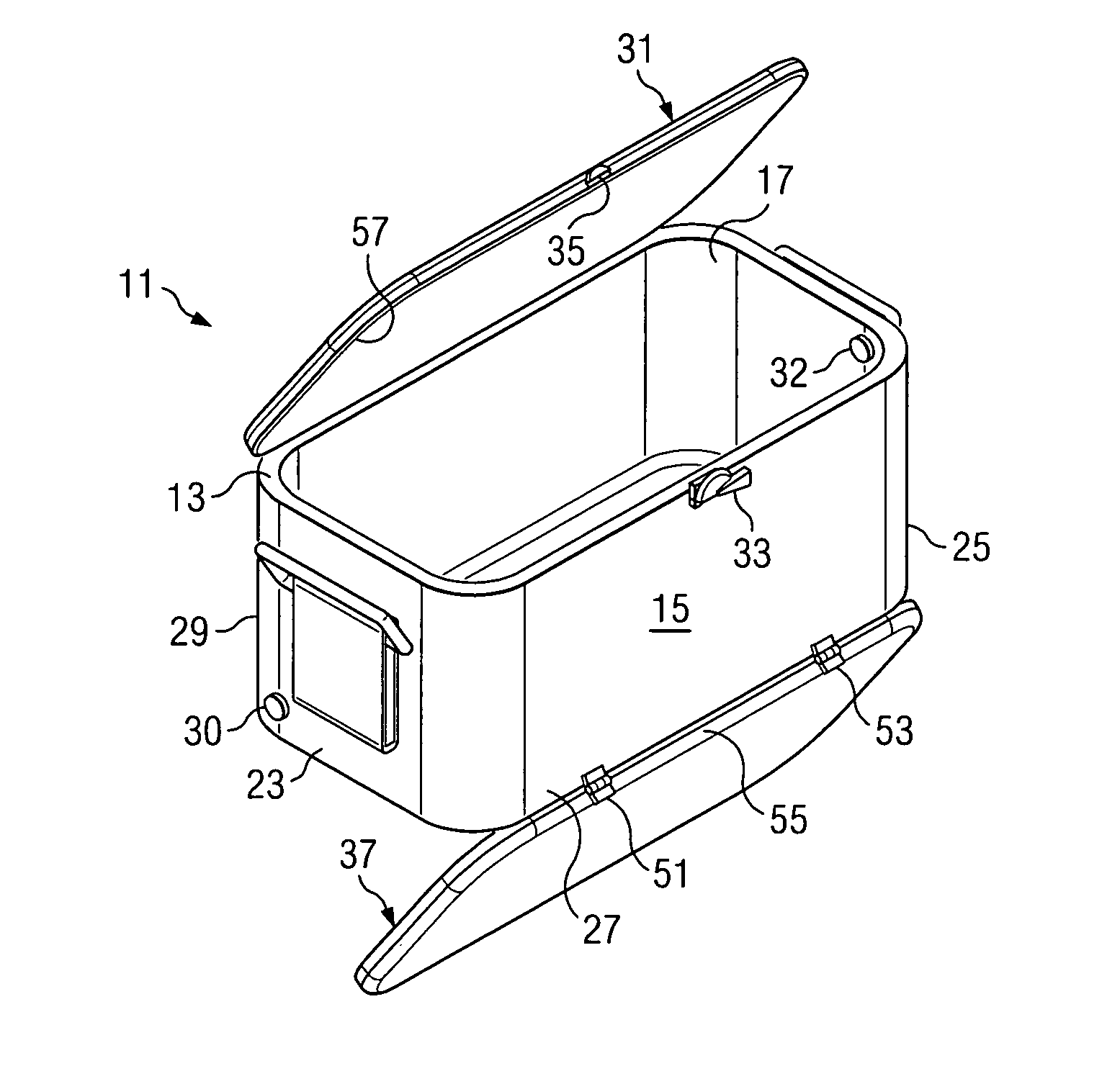
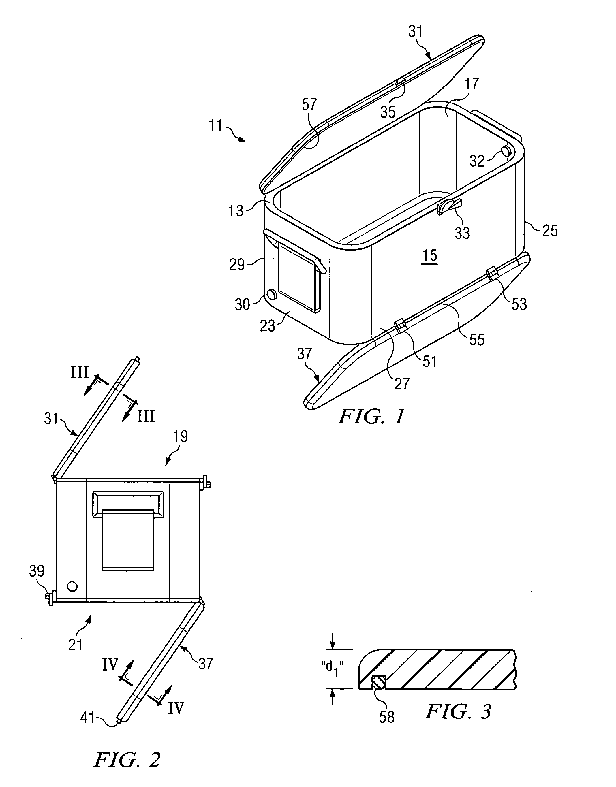
[0025] Turning now to FIG. 1, there is shown a reversible ice chest of the invention designated generally as 11. The ice chest includes a thermally insulated body 13 having an exterior 15 and an initially open interior 17 which define a top opening 19 and bottom opening 21 (FIG. 2) for the body. The particular ice chest 11 illustrated in FIG. 1 is intended to be exemplary of the invention. However, as will be apparent from the discussion which follows, the ice chest could take a number of different shapes, sizes and configurations. In any event, the body 13 will be thermally insulated in order to maintain the chest interior temperature relatively constant when a cooling medium, such as ice, is placed within the chest interior 17.

[0026] In the embodiment of FIG. 1, the ice chest 11 is polygonally (rectangularly) shaped being comprised of two pairs of opposing sides 23, 25 and 27, 29, respectively. As can be seen in FIG. 1, a primary lid 31 is movable between an open position (shown ...


PUM


Abstract

A reversible ice chest is shown having oppositely arranged, hinged lids. The lids allow the ice chest to be open and filled from either of two opposite directions. This allows a user to, for example, place drinks to be cooled on top of ice in a half filled chest. The chest would then be turned upside down, thereby covering the drinks with ice. The drinks could be accessed through the lid which is now facing up toward the user.

Description

BACKGROUND OF THE INVENTION [0001] A. Field of the Invention: [0002] The present invention relates to the design of an ice chest or cooler which has oppositely arranged lids on the bottom and top portions thereof to allow the chest to be reversed or flipped in use. [0003] B. Description of the Prior Art [0004] There are a large number of prior art patents on various ice chest and cooler designs. There are also various packing designs in the prior art which feature oppositely arranged lids. For example, U.S. Pat. No. 2,680,535, shows an improved latch mechanism for a double compartmented box which prevents the simultaneous opening of both sides of the box, thereby preventing the accidental spilling of the contents of one side while the other is being used. The box in question does not appear to be used as an ice chest, however. [0005] U.S. Pat. No. 3,061,136, shows a compartmented container for holding small items such as paper clips, stamps and the like, which could be flipped or re...

Claims


Application Information

Patent Timeline
IPC IPC(8): F25D25/00F25D3/08F25D23/00
CPCA45C11/20F25D3/08F25D2500/02F25D2400/16F25D23/02
Inventor FORD, ROBERT G.
Owner FORD ROBERT G
Why Eureka
Try Eureka