
Electric Motor And Series Of Electric Motors

Active Publication Date: 2007-09-13
SEW-EURODRIVE GMBH & CO KG
View PDF18 Cites 25 Cited by
  • Summary
  • Abstract
  • Description
  • Claims
  • Application Information

AI Technical Summary

Benefits of technology

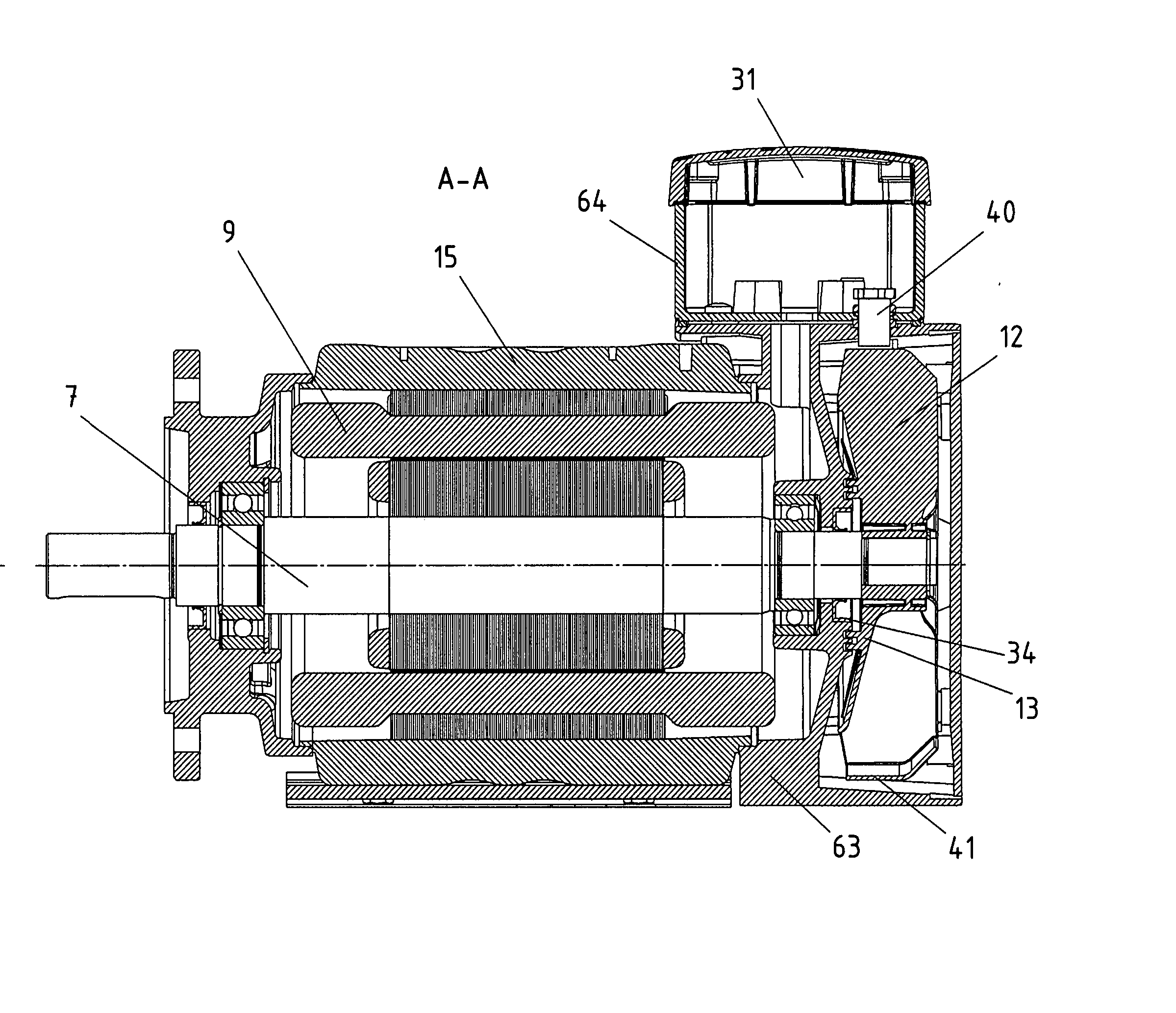
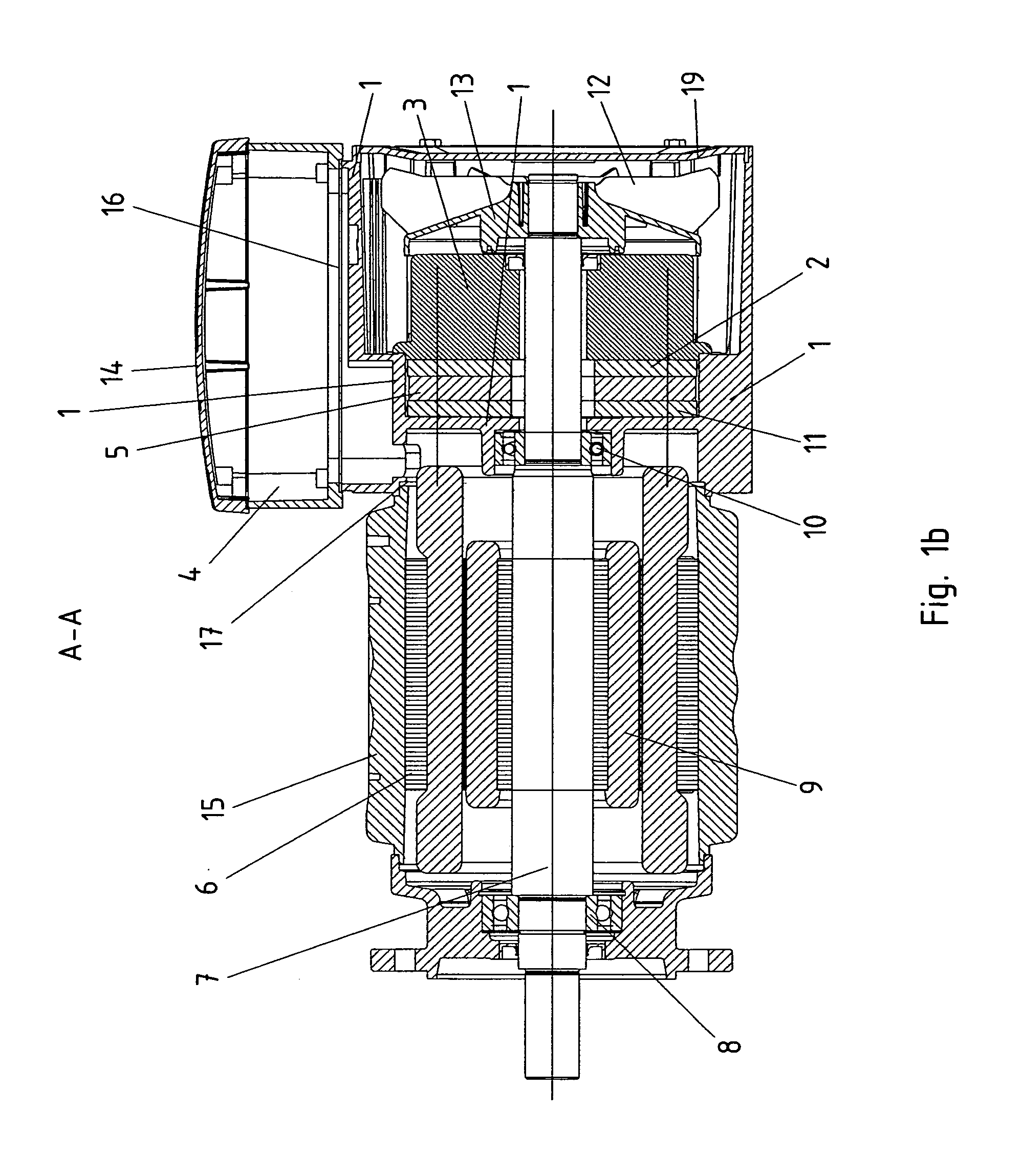
[0009] It may be provided that many different variants may be produced using as few components as possible. A variant, which is as compact as possible, is obtainable for each functional requirement, using as few components as possible. The modular system, i.e., the series, may only provide bearing supports having different interfaces. The housing of the stator remains unchanged. Therefore, it is usable in all of the variants of the series. The interfaces of the bearing support to the housing of the stator allows different bearing supports to be attached. In the case of one of these bearing supports, a terminal box may be integrated. In the case of another, it is detachably connectible and may be alternatively replaced with a converter. The last-named interface to the terminal box may even be oriented to be offset 90° from the interface to the stator. Therefore, it does not have to be coaxially mounted.
[0010] The B-side bearing support, and not the housing of the stator, may be used for variation within the series. It not only allows the stator and rotor plates to be constructed in a substantially identical manner, but also allows, depending on the requirement, different unit volumes of the bearing support to be obtained, together with the terminal box or the converter housing, in the B-side region. However, in the majority of the machines and systems in which electric motors are installed, more volume is available in the B-side region than in the A-side region or in the region over the front axial, i.e., A-side, region of the stator housing. In addition, for maintenance work, easier access is possible in the B-side region than in the A-side region.
[0012] The interfaces of the bearing support are provided for mechanical connection to the above-mentioned parts. In addition, the bearing support also has other functions, e.g., the function of discharging heat of the power electronics from the interior chamber of the terminal box or converter. In each case, the bearing support may always carry out the function of forming a housing for a fan rotating with the rotor shaft. This supplies cool surrounding air and consequently increases the heat flowing from the bearing support to the environment.
[0016] Soft-start electronics may be provided instead of the converter electronics. It may be provided that costs are reducible, since the developmental expenditure of soft-start electronics is less, and they may also be manufactured using fewer components.
[0019] The second bearing support may be arranged to have a sensor, which detects, at the circumference of the fan, physical characteristics of the fan or of a component connected to it. It may be provided that the fan has a larger diameter than the rotor shaft, and that the angular resolution may be consequently improved. In addition, no expensive, complicated sensor system is necessary, but rather a magnetic ring or a magnetic foil is sufficient.

Problems solved by technology

In this context, it is disadvantageous that the converter is thermally insulated in the direction of the motor.
This cooling body is provided on the converter in the direction of the motor and disadvantageously requires a large unit volume.
It is also difficult and expensive to manufacture.
In particular, a design having cooling fingers is associated with high expenditure.
However, in the case of some systems, there is little space available on the side of the motor.
In this context, however, the storage volumes and the costs may become reducible.

Method used


Image

  • Electric Motor And Series Of Electric Motors
  • Electric Motor And Series Of Electric Motors
  • Electric Motor And Series Of Electric Motors

Examples


Embodiment Construction

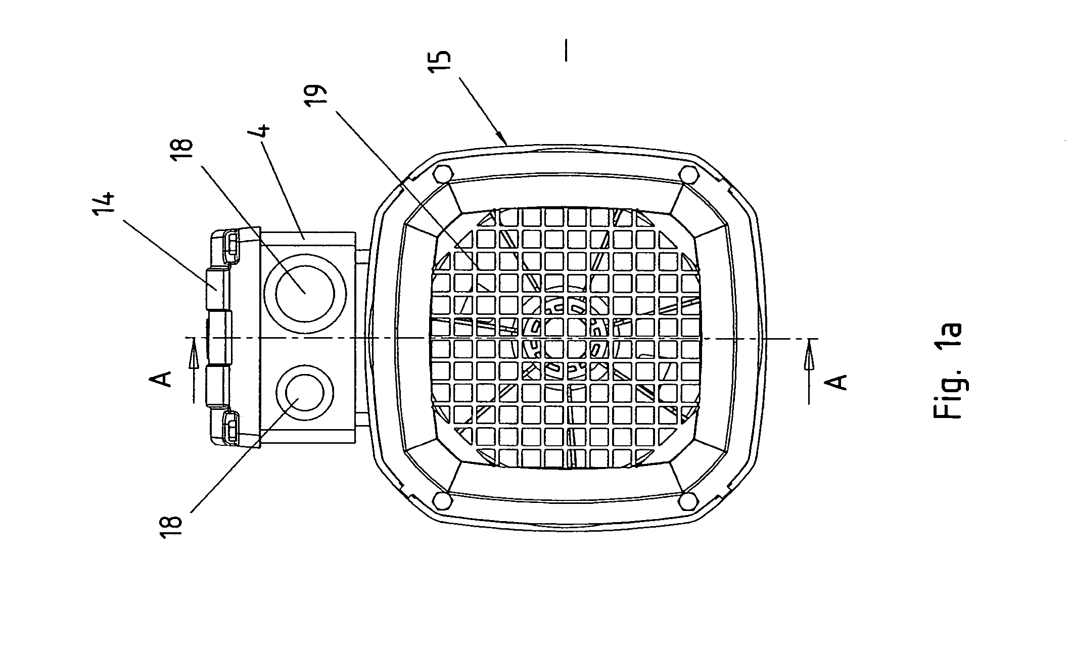
[0077] Illustrated in FIGS. 1a and 1b is the bearing support 1 of an electric motor having a brake. The bearing support has a bearing seat for B-side bearing 10 of the electric motor. The bearing seat is suitably machined for this. The electric motor includes a stator winding 6, which is provided inside housing 15, and a rotor shaft 7, which is supported on the A side by bearing 8 in the A-side bearing support, and on the B side by bearing 10 in the B-side bearing support. Rotor 9, including rotor shaft 7 and rotor plates, is arranged as a squirrel-cage rotor for forming an asynchronous motor. However, the rotor may also be arranged to form a synchronous motor, reluctance motor, or another motor.

[0078] On its B-side end, the rotor shaft supports a fan 13 having fan blades 12. Provided axially in front of this is a brake, which includes a brake coil located in magnet body 3 and an axially movable armature disk 2. When current flows through the brake coil, armature disk 2 is pulled t...


PUM


Abstract

An electric motor and modular system of electric motors includes at least a stator, rotor, and a housing, the modular system including several variants of electric motors, e.g., within one size, the housing having a mechanical interface that is arranged for connection to a bearing support, the bearing support including at least a bearing seat for the B-side bearing of the rotor shaft, at least two different bearing supports being alternatively connectible to the housing, a first bearing support including an additional interface for connection to a bottom part of a terminal box, or alternatively to a bottom part for power electronics, and the first bearing support forming a housing for a brake and / or a fan, a second bearing support being constructed in one piece with a bottom part of a terminal box.

Description

FIELD OF THE INVENTION [0001] The present invention relates to an electric motor and a series of electric motor(s). BACKGROUND INFORMATION [0002] German Published Patent Application No. 197 04 226 describes an electric motor, where an adapter and a cover are put onto the housing of the stator, an electronic circuit having the functionality of a converter being provided in the interior chamber. In this context, it is disadvantageous that the converter is thermally insulated in the direction of the motor. Consequently, a high-power cooling body must be connected to the converter. This cooling body is provided on the converter in the direction of the motor and disadvantageously requires a large unit volume. It is also difficult and expensive to manufacture. In particular, a design having cooling fingers is associated with high expenditure. [0003] The terminal box, i.e., connection box, of the electric motor is not axially mounted, but laterally. However, in the case of some systems, th...

Claims


Application Information

Patent Timeline
IPC IPC(8): H02K9/06H02K3/24H02K5/00H02K5/06H02K5/22H02K7/102H02K9/14H02K11/04
CPCH02K5/06H02K5/225H02K11/0073H02K9/14H02K7/1025H02K11/33
Inventor SCHMIDT, JOSEFBECKER, GUNTERPFANN, JOCHENTRONDLE, KARL-HEINZ
Owner SEW-EURODRIVE GMBH & CO KG
Learn More