Hot forming line and method for producing a hot formed and press hardened motor vehicle part

a technology of hot forming line and press hardening, which is applied in the direction of quenching device, furnace type, shaping tool, etc., can solve the problems of low production cost of parts and retrofitting work, and achieve high acquisition cost, simple temperature treatment plate exchange, and flexible use

Active Publication Date: 2014-05-08
BENTELER AUTOMOBILTECHNIK GMBH
View PDF7 Cites 21 Cited by
  • Summary
  • Abstract
  • Description
  • Claims
  • Application Information

AI Technical Summary

Benefits of technology

[0010]A further important advantage of the present invention is that the high acquisition costs of the tool with corresponding temperature treatment devices and corresponding closing mechanics are only incurred once and the temperature treatment device can then be used flexibly in a broad range of applications by simple exchange of the temperature treatment plates. Thus, only the temperature treatment plates have to be renewed or exchanged but not the entire temperature treatment device. As a result, cumbersome retrofitting work is not required, and the production costs of the parts are kept low.
[0011]The temperature treatment plates may extend over the entire surface of the upper tool and / or the lower tool so that in the case of a blank a hollow space is formed between the temperature treatment plates when closing the temperature treatment device, which hollow space essentially covers the entire plate.
[0012]According to another advantageous feature of the present invention, the temperature treatment plates can be configured flat for temperature treatment of a sheet blank or three-dimensionally, wherein a hollow space remains between the temperature treatment plates when the temperature treatment station is closed. In the case of temperature treatment plates with flat configuration it is thus possible to conductively temperate, in particular heat a sheet metal blank by top-side contact with the temperature treatment plate on the upper tool and bottom-side contact with the temperature treatment plate on the lower tool.
[0013]According to another advantageous feature of the present invention, preformed parts may be heated by the three-dimensionally configured temperature treatment plates, wherein the hollow space between the temperature treatment plates of the closed temperature treatment station essentially corresponds to the contour of the already preformed part. In this regard it is further advantageous that the part is held centered and with this is fixed during the conductive temperature treatment thereby avoiding deformation.
[0014]According to another advantageous feature of the present invention, a temperature treatment source can be arranged in the upper and / or the lower tool. A temperature treatment source is in particular configured as electric resistance heating source or as burner or as inductive heat source. The temperature treatment source is integrated in or arranged on the upper or lower tool so that by exchanging the temperature treatment plate a heating preferably exclusively of the temperature treatment plate itself occurs. This reduces the energy required for heating the part to the essential amount so that by the at least regional contact a fast and efficient temperature treatment, in particular a heating of the sheet metal blank and / or the part occurs. In the case of an electric resistance heating, the temperature treatment plate is configured in a first embodiment especially preferably so that the temperature treatment plate is configured itself as electric resistor, wherein by applying a voltage essentially only the temperature treatment plate is heated but not the upper or the lower tool. As an alternative, an electric resistance heating source is arranged on the upper tool or lower tool so that by coupling with the temperature treatment plate a heating of the temperature treatment plate via the electric resistance heat source occurs.
[0015]When a burner is used the burner is preferably operated with fossil fuels as a fuel oil burner, wherein the burner is preferably arranged on the upper or lower tool so that its flame is directed to the temperature treatment plates to be coupled. Corresponding supply air and exhaust air for the combustion are then integrated in the upper tool or the lower tool.

Problems solved by technology

As a result, cumbersome retrofitting work is not required, and the production costs of the parts are kept low.

Method used


Image

  • Hot forming line and method for producing a hot formed and press hardened motor vehicle part
  • Hot forming line and method for producing a hot formed and press hardened motor vehicle part
  • Hot forming line and method for producing a hot formed and press hardened motor vehicle part

Examples


Embodiment Construction

[0054]Throughout all the Figures, same or corresponding elements are generally indicated by same reference numerals. These depicted embodiments are to be understood as illustrative of the invention and not as limiting in any way. It should also be understood that the drawings are not necessarily to scale and that the embodiments are sometimes illustrated by graphic symbols, phantom lines, diagrammatic representations and fragmentary views. In certain instances, details which are not necessary for an understanding of the present invention or which render other details difficult to perceive may have been omitted.

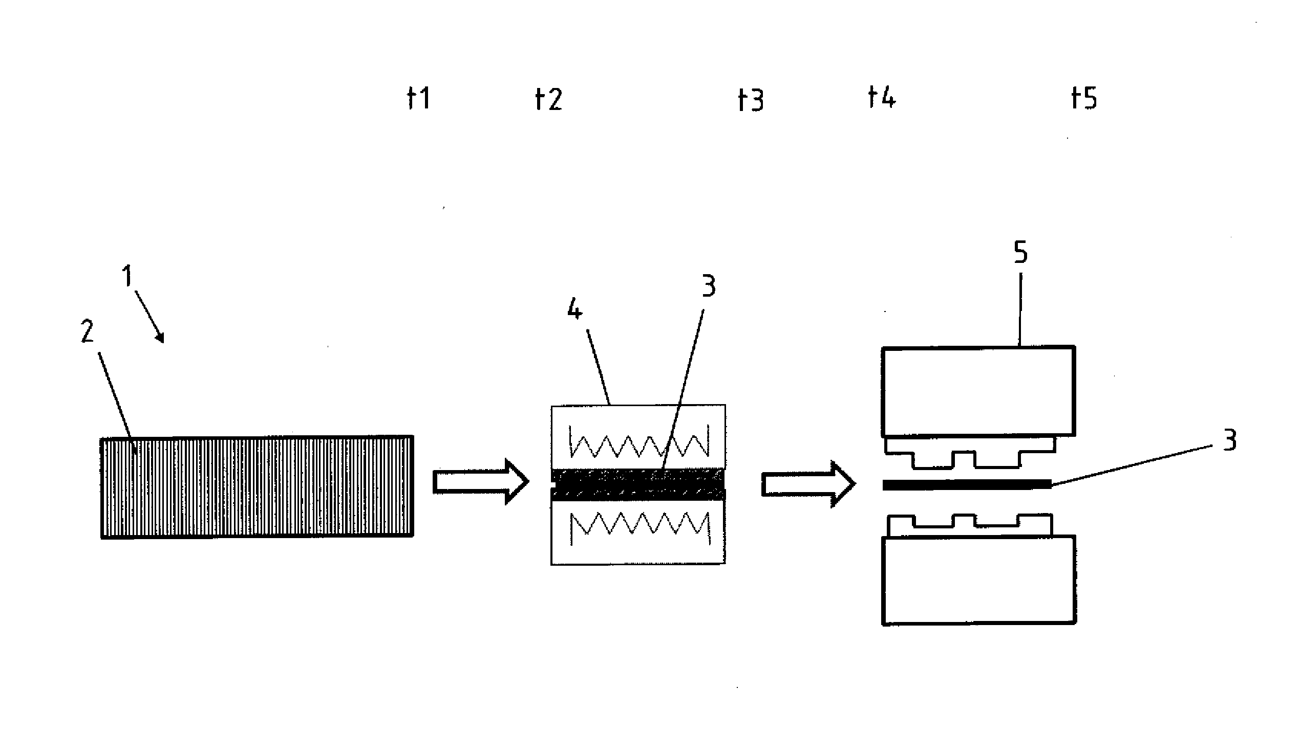
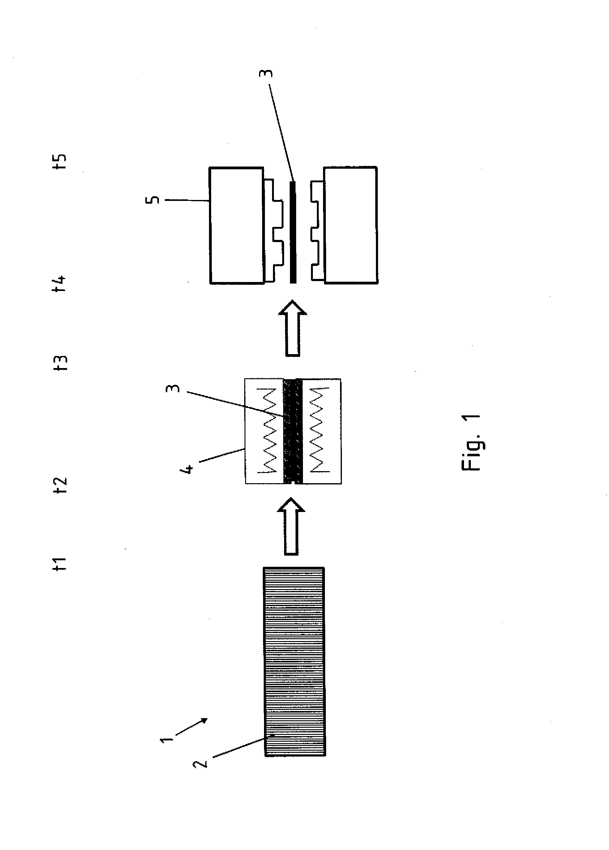
[0055]Turning now to the drawing, and in particular to FIG. 1, there is shown a hot forming line 1 according to the invention, wherein the hot forming line 1 has a furnace 2 for homogenously heating a blank 3. After the heating in the furnace, the blank 3 is transferred into a temperature treatment station 4 according to the invention for the here shown targeted post-heating. ...


PUM

PropertyMeasurementUnit
temperatureaaaaaaaaaa

Abstract

A hot forming line for producing hot formed and press hardened steel sheet products, includes: a forming device; a heating device having a temperature treatment station, wherein the temperature treatment station includes an upper tool and a lower tool, and at least one temperature treatment source; and exchangeable temperature treatment plates for conductive temperature treatment of a blank or part inserted into the temperature treatment station, wherein the exchangeable temperature treatment plates are constructed for arrangement on the upper tool and/or the lower tool, and the temperature treatment source is constructed for heating or cooling the temperature treatment plates. The temperature treatment station is constructed for treating different regions of the blank or part with different temperatures by conductive contact of the temperature treatment plates with the blank of part.

Description

CROSS-REFERENCES TO RELATED APPLICATIONS[0001]This application claims the priority of German Patent Application, Serial No. 10 2012 110 649.5, filed Nov. 7, 2012, pursuant to 35 U.S.C. 119(a)-(d), the disclosure of which is incorporated herein by reference.BACKGROUND OF THE INVENTION[0002]The present invention relates to a hot forming line and method for producing a hot formed and press hardened motor vehicle part[0003]The following discussion of related art is provided to assist the reader in understanding the advantages of the invention, and is not to be construed as an admission that this related art is prior art to this invention.[0004]It is known from the state of the art to produce motor vehicle bodies from metallic materials. For this, in particular steel materials or lightweight metal materials are used. In recent years high-strength and ultra high-strength steel materials were used which have at least partially high strengths or ductile properties so that the strength and t...

Claims


Application Information

Patent Timeline
Patent Type & Authority Applications(United States)
IPC IPC(8): B21D22/02C21D8/00
CPCC21D8/005B21D22/022C21D1/185C21D1/673C21D9/46C21D1/34C21D2221/00C22C38/002C22C38/02C22C38/04C22C38/06C22C38/12C22C38/14C21D9/0062C21D1/18C21D8/00C21D1/42C21D1/40C22C38/44C22C38/48C22C38/50C22C38/54Y02P10/25
Inventor TRIPPE, CARSTENWULFES, DIETERADELBERT, STEFANDANGER, ELISABETH
Owner BENTELER AUTOMOBILTECHNIK GMBH
Why Eureka
Try Eureka