Vehicular hydraulic braking supercharger and braking pressure distributing system

A hydraulic brake and supercharger technology, which is applied in the direction of brakes, brake transmissions, vehicle components, etc., can solve problems such as hidden dangers of unloading spring failure, eliminate hidden dangers of booster function disappearance, and improve safety and reliability The effect of low resistance and processing difficulty

Active Publication Date: 2016-05-25
TAICANG RONGCHI MOTOR
View PDF5 Cites 0 Cited by
  • Summary
  • Abstract
  • Description
  • Claims
  • Application Information

AI Technical Summary

Problems solved by technology

[0005] In order to solve the problem of potential failure of the unloading spring, the present invention provides a hydraulic brake booster, including: a booster piston rod, a housing, a return spring and a sealing ring for the hole, and the booster piston rod is provided with a large end and the small end, the small end diameter is D 2 , the big end diameter is D 1 and D 1 >D 2 ; The housing is sequentially provided with a brake fluid input port, a low-pressure chamber, a high-pressure chamber, and a high-pressure brake fluid output port, and the brake fluid input port, low-pressure chamber, high-pressure chamber, and high-pressure brake fluid output port are sequentially arranged The low-pressure chamber and the high-pressure chamber are collectively called the inner chamber; the booster piston rod is axially slidably installed in the inner cavity of the housing, the large end of the booster piston rod matches the low-pressure chamber, and the small end of the piston rod matches the high-pressure chamber. Cooperate; the sealing ring for the hole is installed on the big end of the booster piston rod to seal the booster piston rod and the inner peripheral wall of the low-pressure chamber, the return spring is installed between the booster piston rod and the inner cavity of the housing, and the booster piston rod is in the position of the return spring Under the action of elastic force, it leans against the inner end wall of the low-pressure chamber of the housing; it is characterized in that: the booster piston rod is provided with a first through hole communicating with the high-pressure chamber, and the first through hole is connected to the side circumference of the booster piston rod. The first extraction hole on the surface is connected, and the second extraction hole is provided on the inner peripheral wall of the housing cavity. The housing or the booster piston rod is provided with a second through hole that communicates with the brake fluid input port. The second through hole The hole communicates with the second outlet hole; in the free state, the first outlet hole is in contact with the second outlet hole and communicates with the high-pressure chamber and the brake fluid input port, and the pressure boosting piston rod is subjected to the pressure difference between the low-pressure chamber and the high-pressure chamber. After the high-pressure chamber advances, the first lead-out hole and the second lead-out hole are staggered, and the inner peripheral wall of the housing cavity covers the first lead-out hole, cutting off the passage between the high-pressure chamber and the brake fluid input port

Method used


Image

  • Vehicular hydraulic braking supercharger and braking pressure distributing system
  • Vehicular hydraulic braking supercharger and braking pressure distributing system
  • Vehicular hydraulic braking supercharger and braking pressure distributing system

Examples


Embodiment 1

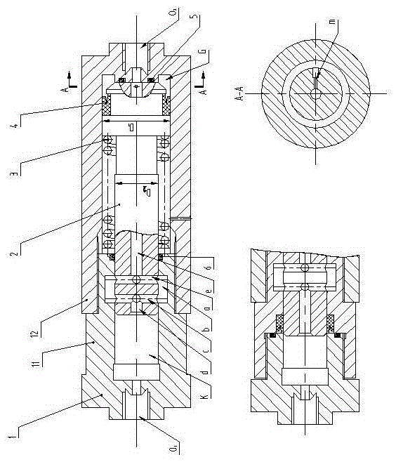
[0017] control figure 1 The first embodiment of the hydraulic brake booster of the present invention will be described in detail.

[0018] The hydraulic brake booster includes a housing 1, a booster piston rod 2, a return spring 3 and a sealing ring 4 for the hole. The booster piston rod 2 is provided with a large end and a small end, and the diameter of the small end is D 2 , the big end diameter is D 1 and D 1 >D 2 ; The housing 1 is composed of a high-pressure chamber housing 11 and a low-pressure chamber housing 12, which are connected by threads. The high-pressure brake fluid output port O is set on the high-pressure chamber housing 11 1 and the high-pressure chamber K, and the brake fluid input port O is set on the low-pressure chamber housing 12 2 and low-pressure chamber G, after housing 1 is assembled, the brake fluid input port O 2 , low-pressure chamber G, high-pressure chamber K, high-pressure brake fluid output port O 1 The low-pressure chamber G and the hi...

Embodiment 2

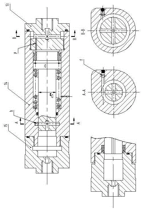
[0029] figure 2 It is another embodiment of the hydraulic brake booster of the present invention.

[0030] The forms of the first through hole and the first lead-out hole in this embodiment are the same as those in the previous two embodiments. The form of the second lead-out hole is an annular groove b corresponding to the first lead-out hole, and the second through hole consists of a hole f drilled in the axial direction of the housing 1 and a radially drilled hole corresponding to the position of the ring groove b h, brake fluid input port O 2 It communicates with hole h.

[0031] figure 2 Among them, the housing 1 includes an end cover 13, and the end cover 13 is provided with a low-pressure brake fluid input hole O 2 , the input hole O 2 Communicate with the second through hole.

[0032] The throttle hole is in the form of a hole p processed axially along the end cover 13, and the hole p is connected with the low-pressure brake fluid input hole O 2 connected. In...

Embodiment 3

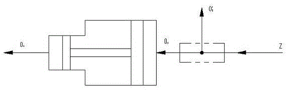
[0037] image 3 It is a working principle diagram when the vehicle brake control system is constructed by adopting the above embodiments.

[0038] booster and tee fittings ( image 3 The part surrounded by double dotted lines) constitutes the brake pressure distribution system. The low-pressure brake fluid is input from the Z port, divided into two routes through the three-way pipe joint, and one route is O’ 2 The port outputs low-pressure brake fluid to the low-pressure wheel brake cylinder, and the other path passes through the supercharger from O 1 Output high-pressure brake fluid to the high-pressure brake wheel cylinder.

[0039] The braking method shown in this embodiment is also a general implementation mode when the existing hydraulic brake booster needs to distribute high and low pressure brake fluid, and its characteristic is that a three-way pipe joint or similar parts must be used to realize pressure division.


PUM


Abstract

The invention relates to a vehicular hydraulic braking supercharger and a braking pressure distributing system, belonging to the field of the vehicular hydraulic braking part and system. A first leading hole and a second leading hole are matched to control communication and disconnection between a high pressure cavity and a brake fluid input port, and an unloading spring (or a pressure spring) is not needed; therefore, a hidden danger of disappearance of the supercharging function, caused by the fault of the unloading spring, is radically eliminated during use, and the safety and the reliability are improved. The supercharger and a three-way pipe coupling constitute the braking pressure distributing system.

Description

technical field [0001] The invention relates to a brake pressure distribution system of a vehicle hydraulic brake supercharger, which belongs to the field of vehicle hydraulic brake components and systems. Background technique [0002] At present, brake boosters, such as vacuum boosters and pneumatic boosters, are widely used in vehicle hydraulic braking systems at home and abroad. The power can reduce the driver's brake pedal force, and the effect is good, but the structure is complicated, the volume is large, the maintenance is difficult, and the power assist function will be lost after the engine is turned off. [0003] The existing hydraulic brake booster (or booster) uses the booster piston rod to make the output port output a higher pressure, avoiding the shortcomings of other boosters relying on the power source of the automobile engine; but when it is working, the booster Pressure control uses the unloading valve controlled by the unloading spring (or the slide valv...

Claims


Application Information

Patent Timeline
Patent Type & Authority Applications(China)
IPC IPC(8): B60T13/128
CPCB60T13/12
Inventor 吕冰张世俊
Owner TAICANG RONGCHI MOTOR
Why Eureka
Try Eureka