
Vehicle occupant system having an adaptive knee airbag

a technology of adaptive knee airbags and occupant restraint systems, which is applied in the direction of vehicular safety arrangements, pedestrian/occupant safety arrangements, vehicular components, etc., and can solve the problem of maintaining the minimum internal pressure of the knee airbag

Active Publication Date: 2014-05-08
TRW AUTOMOTIVE GMBH
View PDF14 Cites 16 Cited by
  • Summary
  • Abstract
  • Description
  • Claims
  • Application Information

AI Technical Summary

Benefits of technology

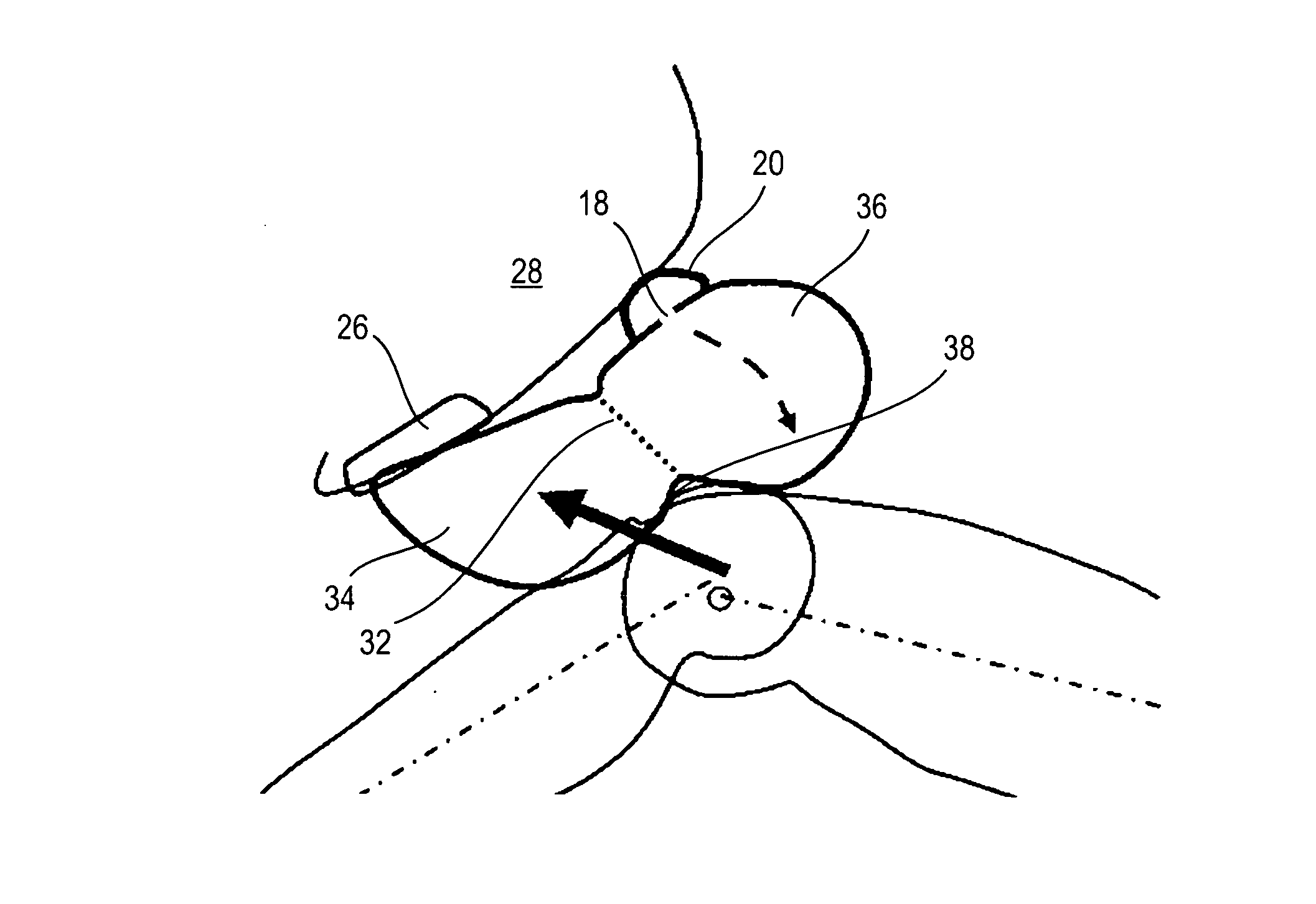
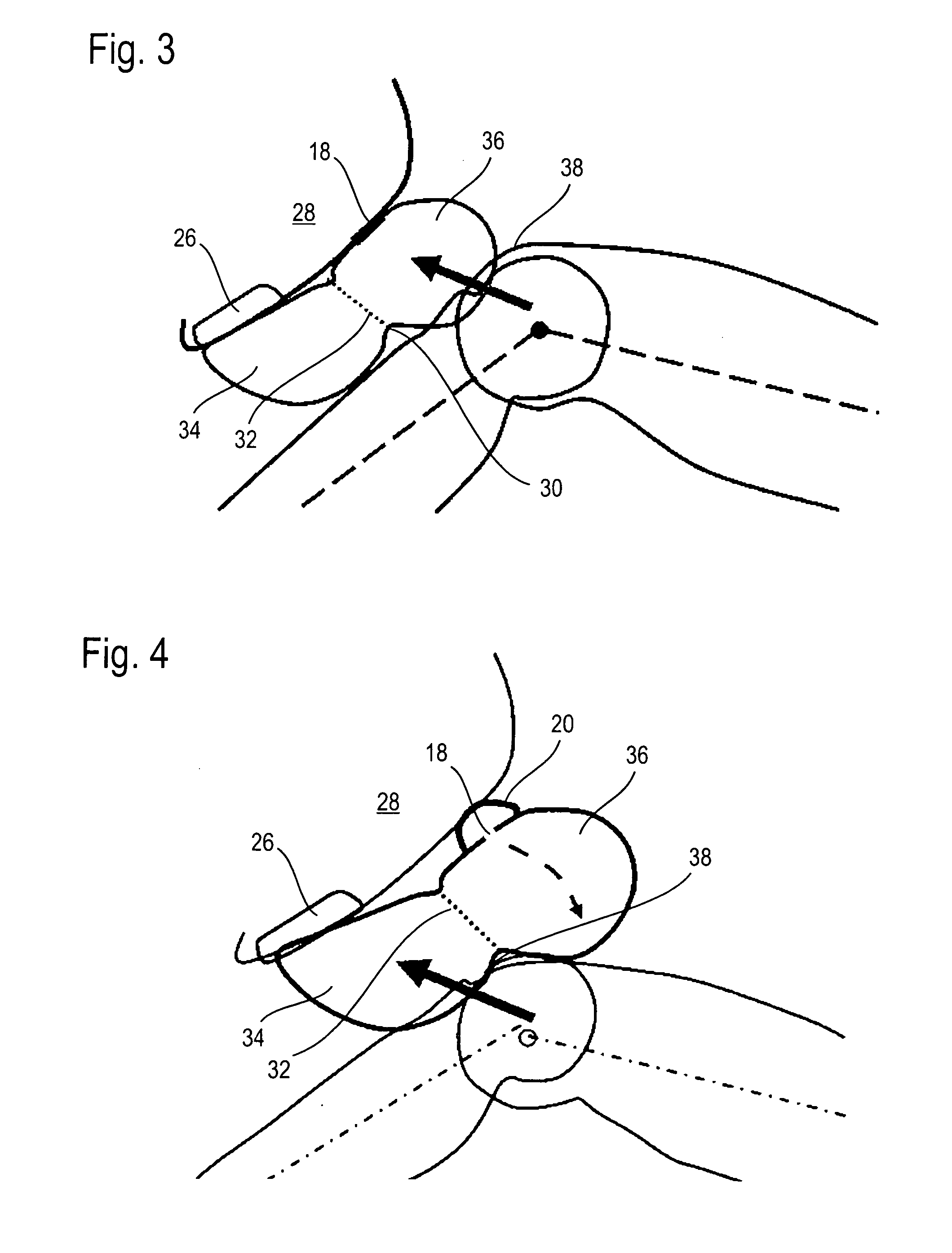
The invention is about improving the protective effect of knee airbags in vehicles by adjusting their internal pressure to the physical constitution of the occupant. This can be done at a lower cost compared to active solutions that require electronics and multi-stage inflators. The knee airbag should always inflate to the same amount, regardless of the occupant's size, so a small occupant's knees do not close the vent hole and gas can flow out of the airbag. The internal pressure is reduced and a better damped restraint behavior is permitted. In a special embodiment, multiple vent holes can be provided to further adapt the internal pressure and plural vent passages can be provided to direct the gas flow away from the occupant. This allows for a space-saving design and ensures a predetermined size of the vent passage even if the airbag is in close contact with the instrument panel.

Problems solved by technology

However, as soon as the deployed passenger airbag covers the vent hole, the gas discharge from the vent hole is restricted so that a minimum internal pressure of the knee airbag is maintained for a quite long period of time.

Method used


Image

  • Vehicle occupant system having an adaptive knee airbag
  • Vehicle occupant system having an adaptive knee airbag
  • Vehicle occupant system having an adaptive knee airbag

Examples


Embodiment Construction

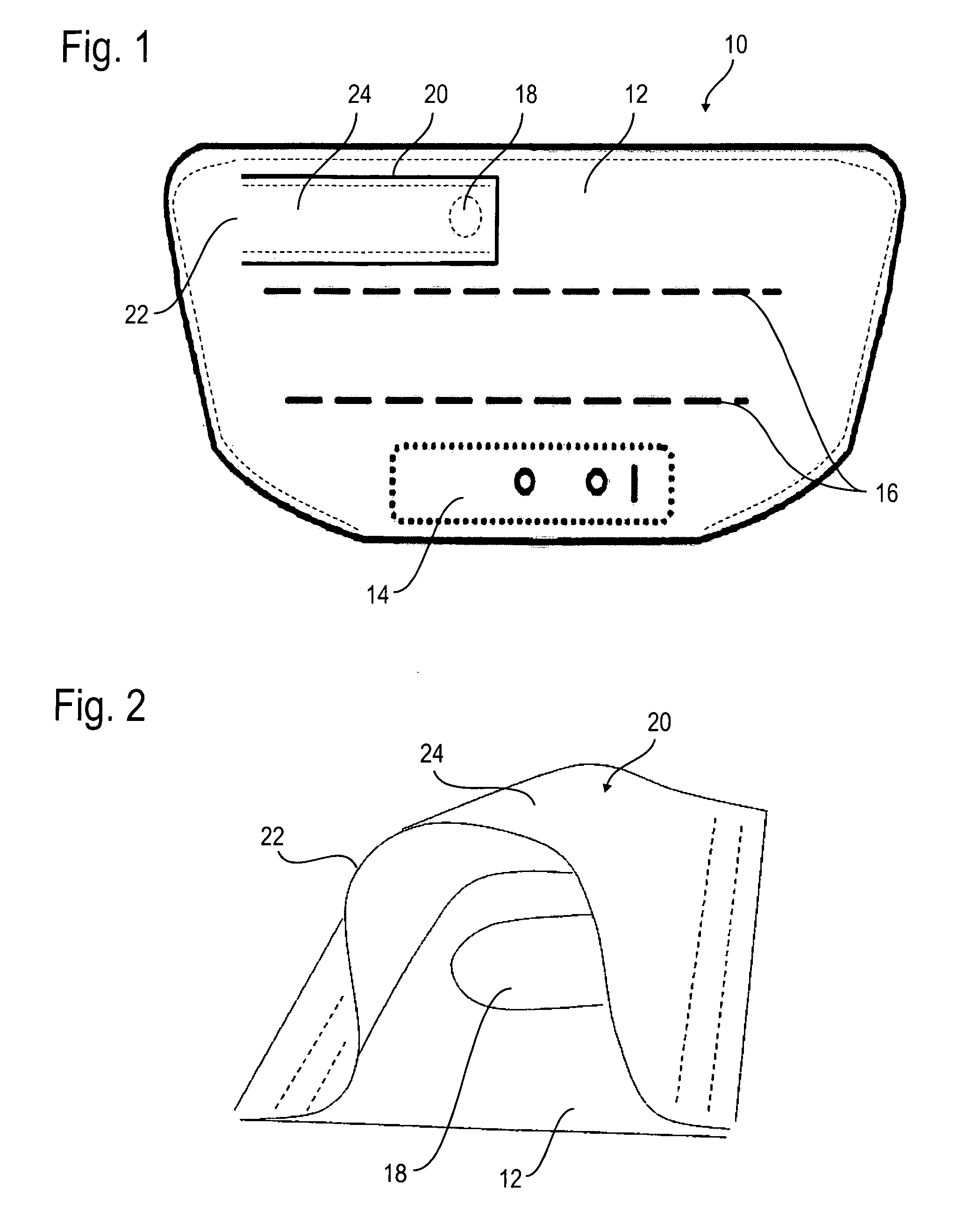
[0041]FIG. 1 illustrates a knee airbag 10 for a vehicle occupant restraint system according to a first embodiment comprising an airbag sheath 12 having a connecting zone 14 for an inflator and connecting points 16 for one or more tethers. Furthermore the airbag sheath 12 includes a vent hole 18 which is substantially circular and preferably has a diameter between 20 mm and 40 mm.

[0042]The vent hole 8 is covered by a cover 20 in the form of a flexible fabric layer or another not dimensionally stable material which, with the exception of a venting section 22 around the vent hole 18, is fastened to the airbag sheath 12. The cover 20 is fastened so that a passage portion 24 of the cover 20 located above the vent hole 18 can bulge. Thus said passage portion 24 together with the part of the airbag sheath 12 located there below can define a vent passage for the gas provided inside the knee airbag 10 in the inflated condition of the knee airbag 10, as shown in FIG. 2. For this purpose, the ...


PUM


Abstract

A vehicle occupant restraint system comprises an inflatable knee airbag (10). The knee airbag (10) includes an airbag sheath (12) and at least one vent hole (18) formed therein. The vent hole (18) is arranged in the upper half of the knee airbag (10) and is provided on a side of the knee airbag (10) facing away from the vehicle occupant which in the operating position of the knee airbag (10) is directly opposed to a fixed component (28) in the vehicle interior. A method of protecting a vehicle occupant comprises the following steps of: Inflating a knee airbag (10) with gas so that the knee airbag (10) adopts an operating position; and adapting the gas discharge behavior in accordance with the constitution, especially the body height of the vehicle occupant, in that a vent hole (18) formed in an upper section (36) of the knee airbag (10) is pressed against a fixed component (28) in the vehicle interior by the knee (38) of a normal size vehicle occupant moving forward and is closed thereby, or is not pressed against a fixed component (28) in the vehicle interior by the knee (38) of a small size vehicle occupant moving forward.

Description

RELATED APPLICATIONS[0001]This application corresponds to PCT / EP2012 / 002377, filed Jun. 5, 2012, which claims the benefit of German Application No. 10 2011 105 032.2, filed Jun. 8, 2011, the subject matter, of which are incorporated herein by reference in their entirety.BACKGROUND OF THE INVENTION[0002]The invention relates to a vehicle occupant restraint system comprising an inflatable knee airbag. The invention further relates to an automotive vehicle comprising such vehicle occupant restraint system. Finally the invention also relates to a method of protecting a vehicle occupant.[0003]The inflation and discharge behavior of airbags is tested by crash test dummies in impact tests. Crash test dummies are life-size dummies simulating the human body. In order to duly take the different anatomic factors of real persons into account during simulations, the tests are usually carried out with three different dummies. The “50 percent male” having a body height of 175 cm and a weight of 78...

Claims


Application Information

Patent Timeline
IPC IPC(8): B60R21/206B60R21/239
CPCB60R21/239B60R21/206B60R2021/23169B60R2021/2395B60R2021/0051
Inventor ABELE, TIMOFREISLER, WERNER
Owner TRW AUTOMOTIVE GMBH
Learn More