Spiral Guiding Drain Structure

Active Publication Date: 2014-05-15
GLOBE UNION INDAL
View PDF12 Cites 21 Cited by
  • Summary
  • Abstract
  • Description
  • Claims
  • Application Information

AI Technical Summary

Benefits of technology

[0007]The primary object of the present invention is to provide a spiral guiding drain structure w

Problems solved by technology

However, two diameters and two heights of a front end and a rear end of the water feeding are equal, hence the three jet orifices cannot flush the toilet evenly.
Neverthele

Method used


Image

  • Spiral Guiding Drain Structure
  • Spiral Guiding Drain Structure
  • Spiral Guiding Drain Structure

Examples


Example

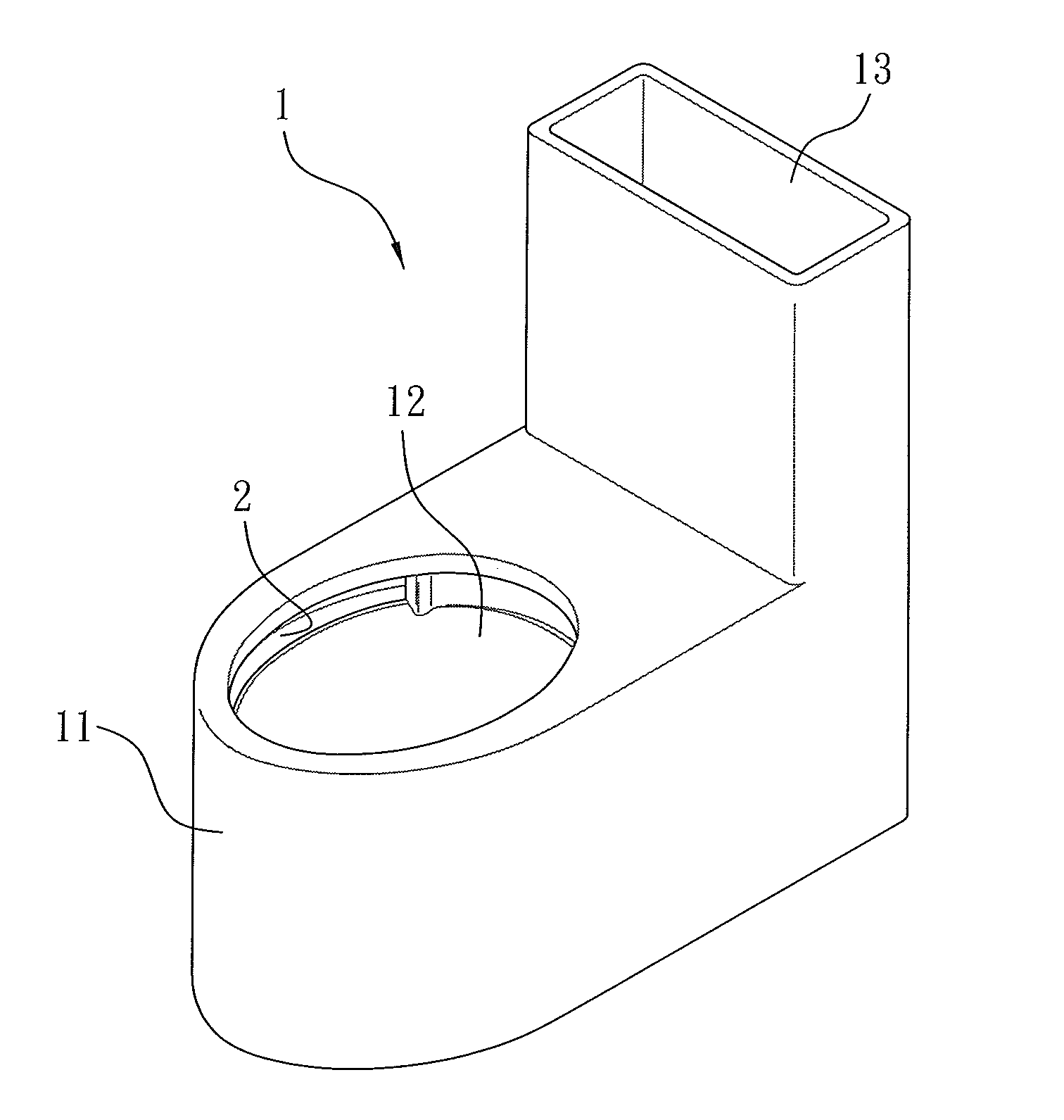
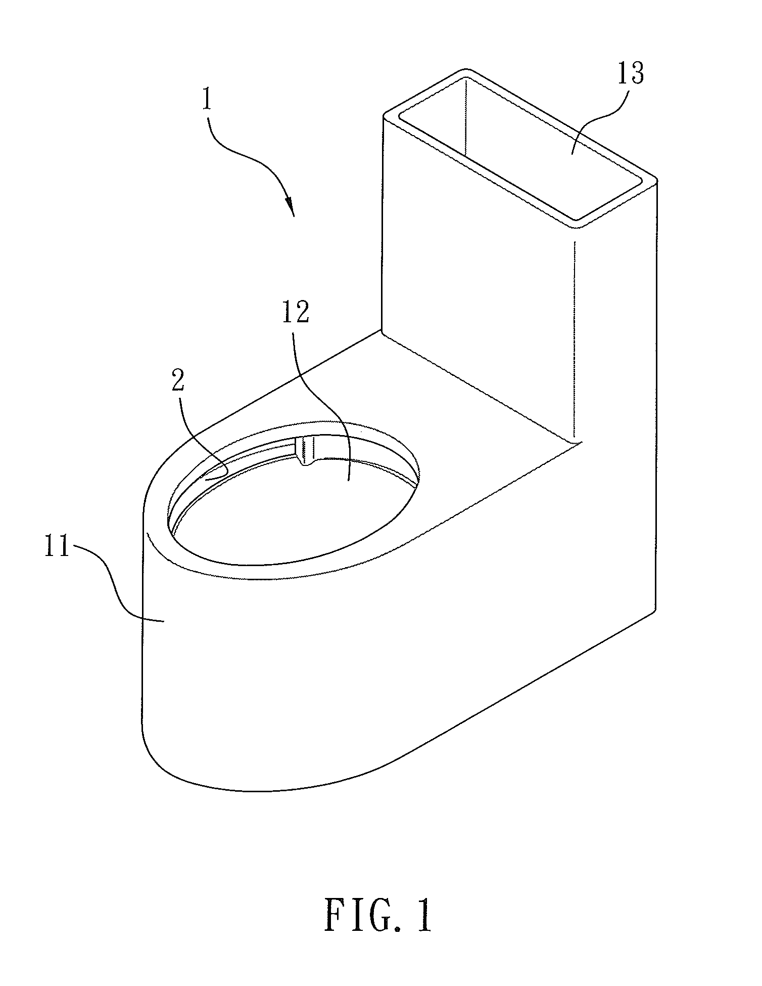
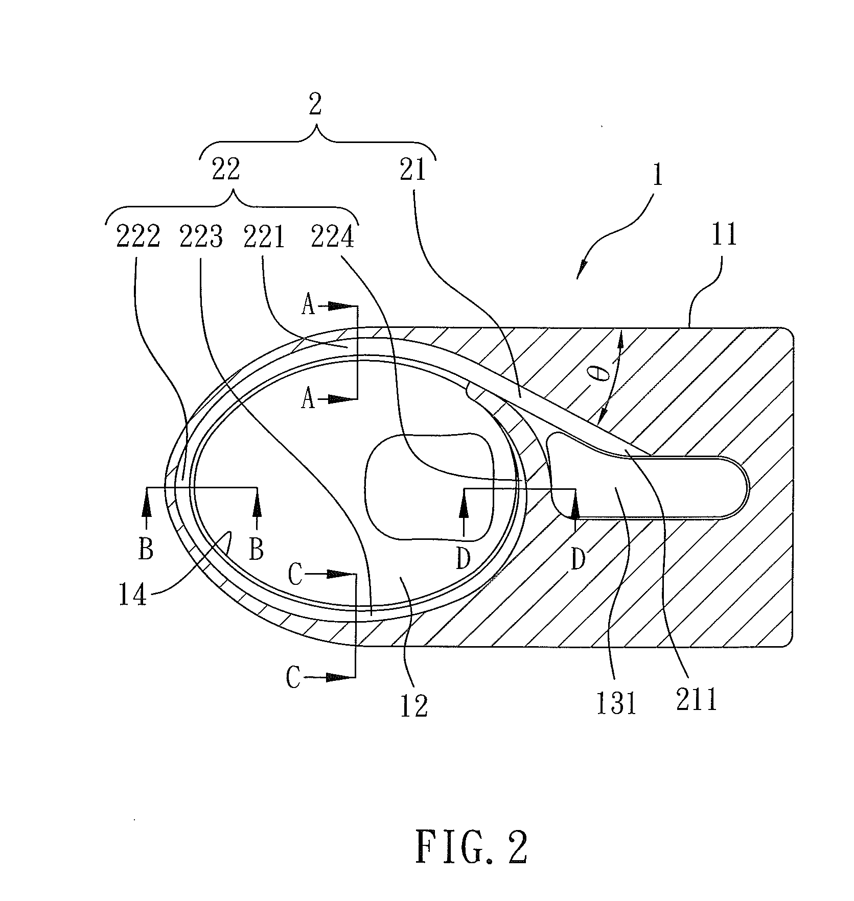
[0028]FIG. 1 is a perspective view showing the assembly of a spiral guiding drain structure according to a preferred embodiment of the present invention. FIG. 2 is a cross sectional view showing the operation of the spiral guiding drains structure according to the preferred embodiment of the present invention. FIG. 3 is a cross sectional view taken along the line A-A of FIG. 2. FIG. 4 is a cross sectional view taken along the line B-B of FIG. 2. FIG. 5 is a cross sectional view taken along the line C-C of FIG. 2. FIG. 6 is a cross sectional view taken along the line D-D of FIG. 2.

[0029]Referring further to FIGS. 1 and 2, a spiral guiding drain structure 2 according to a preferred embodiment of the present invention is disposed on a toilet 1, and the toilet 1 contains a base 11, the base 11 has a basin-shaped inner wall 12 defined therein and a water tank 13 formed on a rear side thereof.

[0030]The spiral guiding drain structure 2 includes a hidden segment 21 and an open segment 22 co...


PUM


Abstract

A spiral guiding drain structure is disposed on a toilet and includes a hidden segment and an open segment connecting with the hidden segment. The hidden segment passes through the toilet and has an inlet end leaving away from the open segment. The open segment is defined on an inner wall of the toilet and spirally surrounds the inner wall downward, a length of the open segment is at least 3/4 circumference of the inner wall of the toilet, and the toilet includes a fence portion extending outwardly from a bottom rim of the open segment adjacent to an opening, and a height of the fence portion changes when an extending distance of the open segment from the hidden segment increases so that water flows out of the open segment, thus flushing the inner wall of the toilet.

Description

FIELD OF THE INVENTION[0001]The present invention relates to a spiral guiding drain structure.BACKGROUND OF THE INVENTION[0002]TW Pat. No. M396294 discloses that a flush toilet structure contains a water feeding pipe surrounding an inner wall of the toilet, and the water feeding pipe has three jet orifices defined on the water feeding pipe so that a jet range of a respective one of the three jet orifices is 120 degrees, thus flushing an inner wall of the toilet. However, two diameters and two heights of a front end and a rear end of the water feeding are equal, hence the three jet orifices cannot flush the toilet evenly.[0003]TW Pat. No. M245231 discloses that a flush toilet contains a water separating plate fixed on a flushing orifice of the flush toilet so as to flow water from two sides of the flushing orifice, and two projections extend from two sides of the water separating plate so as to guide water to flush an inner wall of the toilet in 180-degree range.[0004]CN Pat. No. 201...

Claims


Application Information

Patent Timeline
IPC IPC(8): E03D11/13
CPCE03D11/13E03D11/02E03D11/08E03D2201/40
Inventor WU, MINGCHIAKUO, CHUNGYULO, TSUNGYIHONG, CHUWAN
Owner GLOBE UNION INDAL
Why Eureka
Try Eureka