Grommet

a technology of grommets and arc sections, applied in the direction of insulating bodies, cable arrangements between relatively moving parts, manufacturing tools, etc., can solve problems such as not applying, and achieve the effects of reducing the insertion force of circular arc sections, reducing the insertion force, and lessening the maximum insertion force of grommets

Active Publication Date: 2006-08-29
SUMITOMO WIRING SYST LTD
View PDF6 Cites 18 Cited by
  • Summary
  • Abstract
  • Description
  • Claims
  • Application Information

AI Technical Summary

Benefits of technology

[0015]According to the structure above, the height from the groove bottom of the first side wall on the insertion side of the large tubular portion is not uniform over the entire periphery, namely lower in the circular arc sections than in the straight sections. The structure thereby reduces the insertion force when inserting and latching the last circular arc section of the body latch groove into an aperture formed in a panel. Specifically, when the large tubular portion of the grommet is inserted to attach to an oval aperture in the panel, the upper end of the first side wall provided along the entire periphery of the large tubular portion is not inserted into the aperture at one time, but inserted in the order of one circular arc section, straight sections on both sides and the other circular section. The insertion order is almost the same for a polygonal shape having circular arcs at corners: the last inserted section is the circular arc section. A high insertion force is then required to insert the last section since other sections of the body latch groove are already fitted into the periphery of the aperture and the large tubular portion is not flexible. The grommet provided in the present invention has a low height in the circular arc sections that require the high insertion force, thereby allowing the circular arc sections to easily pass through the periphery of the aperture and reducing the insertion force. A height from the groove bottom of the first side wall in the straight sections, on the other hand, is set higher than that in the circular arc sections, since the straight sections more easily separate or disengage from the aperture in the panel, thereby providing a higher holding force than in the circular arc sections while not lowering the grommet holding force. As described above, the grommet according to the present invention allows reduction in the grommet insertion force as well as retention of the holding force after attachment to the aperture.
[0017]A grommet having multiple circular arc sections, that is, a grommet attached to an oval aperture, has a pair of straight sections and a pair of circular arc sections. To reduce the insertion force for the last inserted section when attaching the grommet, the height in only one of the pair of circular arc sections, that is, the circular arc section last inserted and latched needs to be low; not the entire height in the circular arc sections needs to be low. Setting only one section height low, however, limits flexibility to insert the grommet, thus deteriorating the workability. Therefore, it is preferable that all circular arc sections have a lower height than the straight sections when a grommet has multiple circular arc sections.
[0019]It is preferable that a second side wall, opposite to the first side wall having the groove bottom therebetween, has a constant height from the groove bottom throughout the peripheral direction. Not passing through an aperture, the second side wall has no impact on insertion force, thus needs no height difference between the straight sections and the circular arc sections. Rather, it is desirable to have the constant height throughout the peripheral direction. According to the structure above, the first and second side walls securely sandwich and hold the periphery of the aperture, even in the circular arc sections of the first side wall where the height from the groove bottom is set low. The structure thus reinforces the holding force of the grommet in the circular arc sections as well, preventing the grommet from coming off from the panel.
[0021]According to the present invention as described above, the grommet has the height from the groove bottom of the first side wall on the insertion end side of the larger tubular portion not uniform along the periphery, that is, lower in the circular arc sections than in the straight sections, which reduces the insertion force for the circular arc sections. Due to the shape that reduces the insertion force, therefore, when inserting and latching the grommet into a aperture, such as an oval shaped aperture, having circular arc and straight sections formed in a panel, a circular arc section, the section last inserted and latched and requiring the maximum insertion force, requires less maximum grommet insertion force. Meanwhile, the height from the groove bottom is higher in the straight sections than in the circular arc sections, since the straight sections tend to detach from the aperture when a pulling force is exerted to a wire harness while the grommet is attached to the aperture. Thereby, the straight sections are provided with deeper latch depth to the periphery of the aperture, strengthening the holding force of the grommet and ensuring prevention of separation or disengagement from the panel. As described above, the grommet according to the present invention meets the conflicting requirements: to decrease the insertion force and to increase the holding force.

Problems solved by technology

Thus, conflicting issues arise herein: reducing the grommet insertion force weakens the holding force; maintaining the holding force does not reduce the insertion force.
The issues apply not only to an oval aperture, but also to an aperture in a polygonal shape having a circular arc at each corner, to which the grommet is attached.

Method used


Image

  • Grommet
  • Grommet
  • Grommet

Examples


Embodiment Construction

[0031]The particulars shown herein are by way of example and for purposes of illustrative discussion of the embodiments of the present invention only and are presented in the cause of providing what is believed to be the most useful and readily understood description of the principles and conceptual aspects of the present invention. In this regard, no attempt is made to show structural details of the present invention in more detail than is necessary for the fundamental understanding of the present invention, the description is taken with the drawings making apparent to those skilled in the art how the forms of the present invention may be embodied in practice.

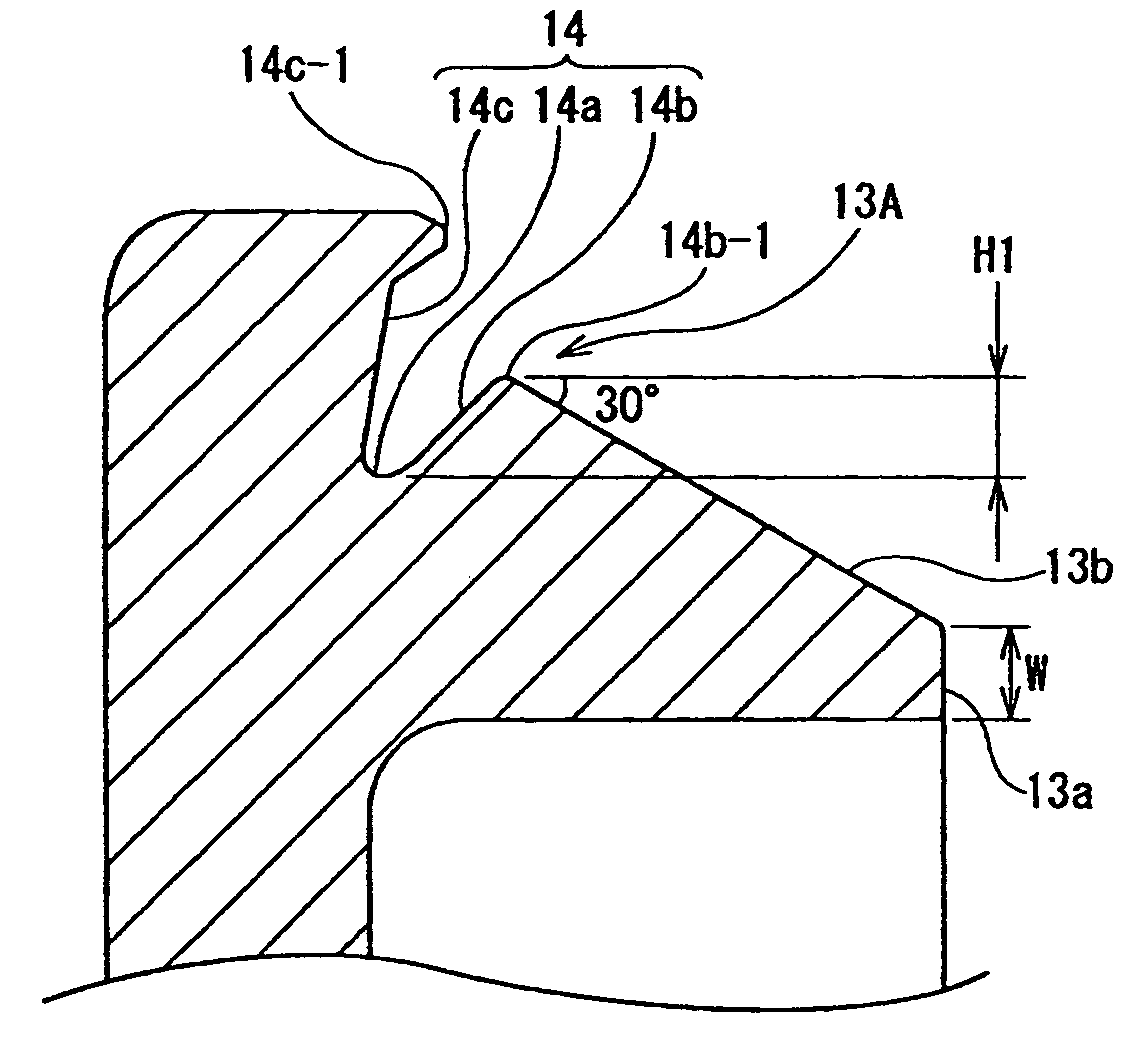
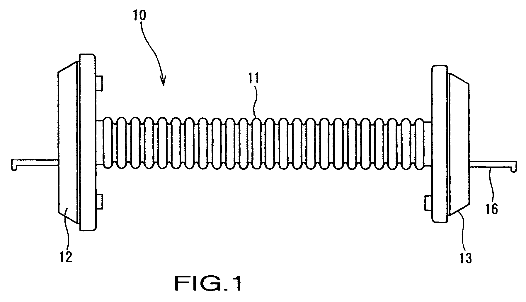
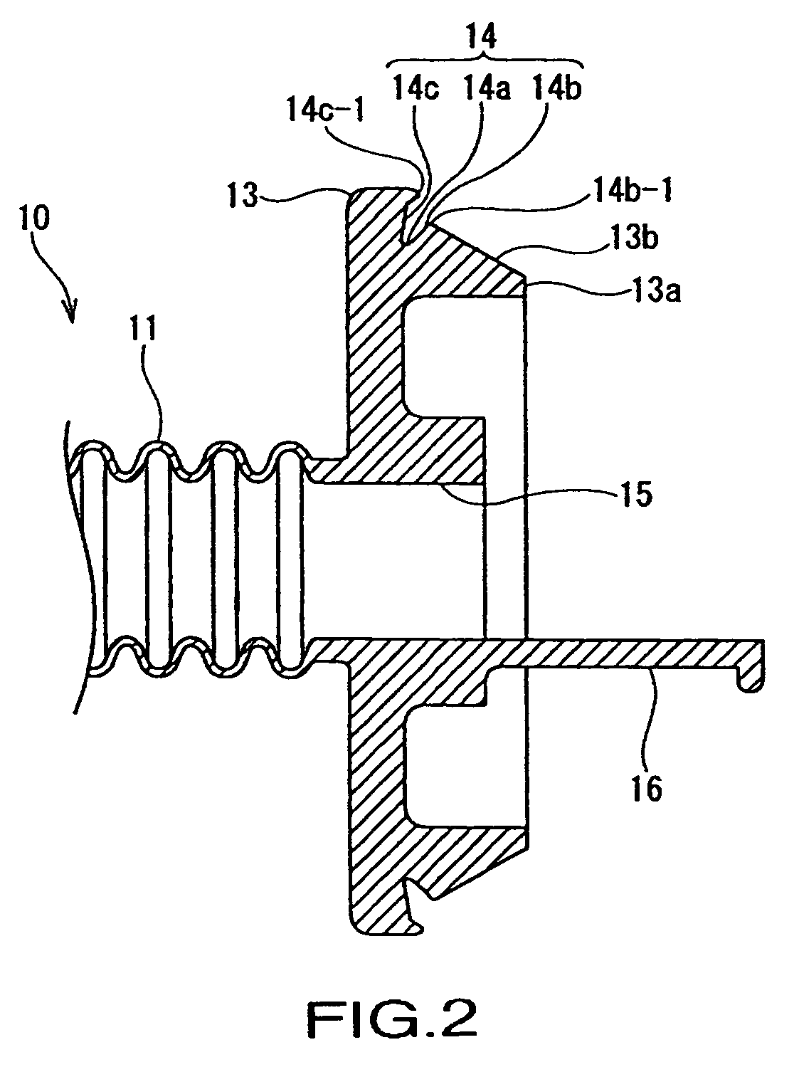
[0032]The following describes preferred embodiments of the present invention with reference to the drawings. FIGS. 1 to 4, 5A, and 5B show an embodiment of the present invention, in which grommet 10 made of a suitable elastic material, such as, for example, rubber or an elastomer, is mounted on wire harness W / H. The wire harne...


PUM


Abstract

A grommet is mounted on a wire harness and inserted and latched into a vehicle panel aperture having a circular arc section at each corner. The grommet has a small tubular portion and a large tubular portion fitting the aperture. The large tubular portion has an annular latch groove having a concave shape on an outer peripheral surface at a predetermined distance from an end. Of two side walls that sandwich a groove base of the latch groove, a first side wall has a height from the groove base greater in straight sections than in arc sections to allow the straight sections to catch a periphery of the aperture more deeply than the arc sections.

Description

CROSS-REFERENCE TO RELATED APPLICATIONS[0001]The present disclosure relates to subject matter contained in priority Japanese Application No. 2004-310423, filed on Oct. 26, 2004, which is herein expressly incorporated by reference in its entirety.BACKGROUND OF THE INVENTION[0002]1. Field of the Invention[0003]The present invention relates to a grommet that reduces the insertion force to attach the grommet to a panel having an aperture, such as a vehicle body panel, while maintaining holding force after attachment to the panel.[0004]2. Description of Related Art[0005]A grommet made of an elastic material, including rubber and elastomer, is mounted on a wire harness routed from an engine compartment to a passenger cabin or a wire harness passed between a body panel and a door panel of a vehicle. The grommet is then attached to the panel at an aperture. The grommet is designed to protect the wire harness passed through the aperture, to shield the cabin from water, dust and noise from th...

Claims


Application Information

Patent Timeline
Patent Type & Authority Patents(United States)
IPC IPC(8): H02G3/18
CPCB60R16/0222H02G11/00Y10T16/05
Inventor SUZUKI
Owner SUMITOMO WIRING SYST LTD
Why Eureka
Try Eureka