Method for producing a cushion element and method and tool for the production thereto

a cushion element and cushion technology, applied in the field of cushion element production, can solve the problems of complicated clamping of the pocket in the die filled with the already foaming flexible foam compound, high cost of the procedure, limited spatial design options, etc., and achieve the effect of simplifying the introduction and improving comfor

Active Publication Date: 2014-05-15
ADIENT US LLC
View PDF3 Cites 5 Cited by
  • Summary
  • Abstract
  • Description
  • Claims
  • Application Information

AI Technical Summary

Benefits of technology

[0018]An advantageous cushion element is distinguished in that the first foamed cushion region is harder than the second foamed cushion region, wherein the upper side of the first foamed cushion region is advantageously designed in the shape of a ramp and such that it rises toward the front edge of the seat. This produces an anti-submarining ramp in a simple and nevertheless effective manner.
[0019]In order to improve the comfort, the second foamed cushion region is preferably designed in such a manner that it at least partially covers the first foamed cushion region from above.
[0020]However, provision may advantageously be made for the first foamed cushion region to extend as far as a surface side, in particular the lower side of the cushion element. This simplifies the introduction of the foamable compound, which is provided for forming the first cushion region, into the die without losses in respect of the comfort having to be accepted. In principle, however, it would also be conceivable to inject the first foamable compound by means of a lance into a separating element which is preshaped to be closed, for example is spherical and which is kept at a distance from the die walls by the abutment during the manufacturing.

Problems solved by technology

Although comfortable cushion elements having different zones of hardness can be manufactured by using said method, the spatial design options are limited.
Furthermore, the clamping of the pocket in the die filled with the already foaming flexible foam compound is complicated.
In this case, the front transverse strut of the frame element is designed to rise to the front in the shape of a ramp and is intended to prevent a seat occupant from plunging under the lap-side strand of the seatbelt (anti-submarining) A procedure of this type is extremely costly because of the high number of components manufactured independently of one another.

Method used


Image

  • Method for producing a cushion element and method and tool for the production thereto
  • Method for producing a cushion element and method and tool for the production thereto
  • Method for producing a cushion element and method and tool for the production thereto

Examples


Embodiment Construction

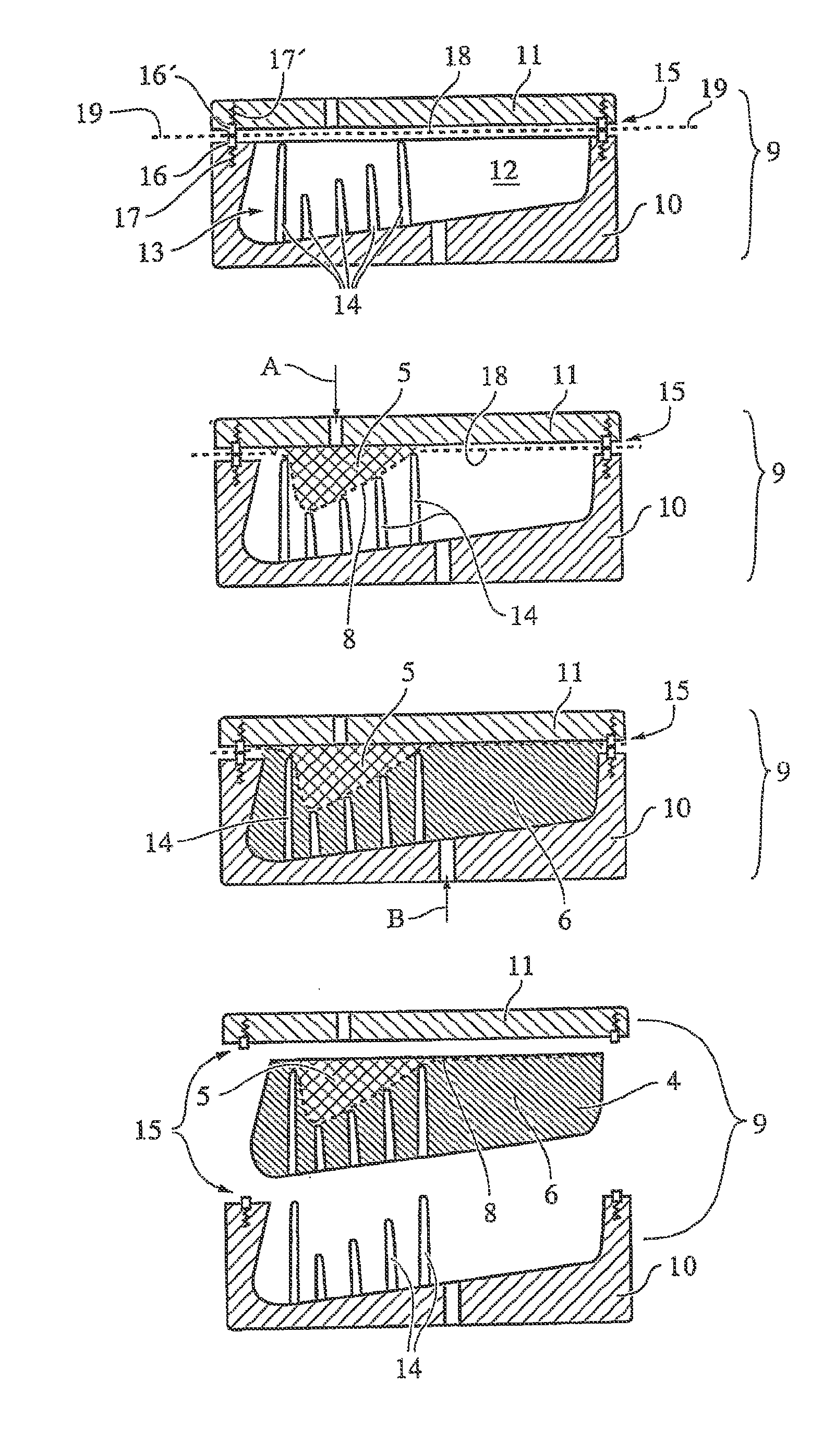
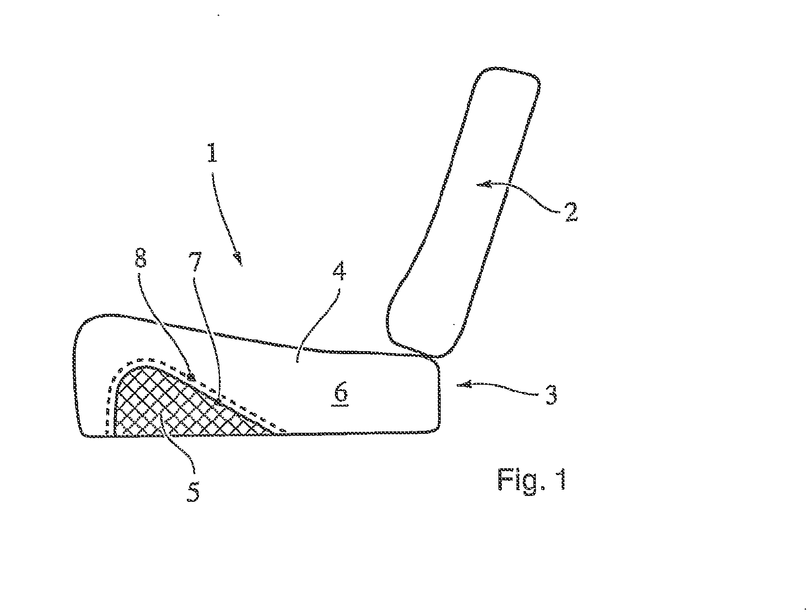
[0028]The motor vehicle seat 1 shown in FIG. 1 consists of a backrest 2 and a seat cushion 3, the cushion element 4 of which has a first foamed cushion region 5 consisting of a relatively rigid foam and a second foamed cushion region 6 consisting of a relatively flexible foam. The rigid cushion region 5 extends substantially in the front part of the cushion element 4. In this case, the upper surface 7 of the cushion region 5 rises in the manner of ramp from the rear to the front and forms a device to prevent the seat occupant from plunging through the seatbelt.

[0029]Directional and positional details refer to the customary installation position of a motor vehicle seat.

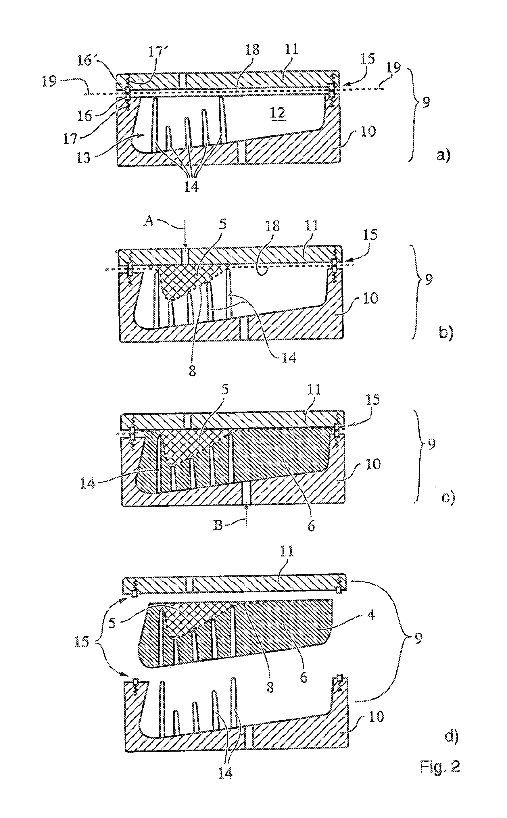
[0030]A textile, three-dimensionally shaped separating element 8 is arranged between the first cushion region 5 and the second cushion region 6, said separating element being gas-permeable but being impermeable to the liquid, foamable compounds provided for forming the cushion regions 5 and 6.

[0031]FIG. 2 illustrates t...


PUM

PropertyMeasurementUnit
foamableaaaaaaaaaa
structureaaaaaaaaaa
gas-permeableaaaaaaaaaa

Abstract

A method for producing a cushion element for a vehicle seat, in which a component suitable for forming a three-dimensional separation zone is inserted in a tool, subsequently at least one first foamable mass is introduced into a first space of the tool. On foaming the mass, the component forms a three-dimensional separating element between a first foamed cushion region and a further space within the tool. The component is pressed against a counter-support in the tool during the forming to give a three-dimensional separating element. A suitable tool comprises an upper tool, a lower tool and a counter support for contacting a component taking on a three-dimensional shape. By introducing the three-dimensional mouldable shape into the tool and the subsequent forming thereof to give a three-dimensional separating element, complex formed regions with differing properties, in particular, differing degrees of hardness can be economically generated in a foamed cushion element.

Description

BACKGROUND[0001]The invention relates to a method for producing a cushion element, in particular for a vehicle seat, in which a component suitable for forming a three-dimensional separating zone is placed into a die and subsequently at least one first foamable compound is introduced into a first space region in the die, wherein, during the foaming of said compound, the component is shaped to form a three-dimensional separating element between a first foamed cushion region and a further space region in the die. The invention furthermore relates to a die suitable for carrying out the method and to a cushion element manufactured therewith.Prior Art[0002]A cushion element of the type mentioned at the beginning is known from laid-open application DE 100 16 350 A1. The cushion element provided for use in seat parts or backrests of vehicle seats consists of a first and a second foamed region, which are separated spatially from each other by a network in the form of a gauze, a nonwoven fabr...

Claims


Application Information

Patent Timeline
Patent Type & Authority Applications(United States)
IPC IPC(8): B60N2/64B60N2/90
CPCB60N2/64B29C44/0469B29L2031/58B29C44/143B29C44/16B60N2/7017B60N2/4263B29C39/12B29C44/04
Inventor STEINMEIER, HORSTHASLER, ALEXANDERSTOLL, DOMINIK
Owner ADIENT US LLC
Why Eureka
Try Eureka