
Avionics Method and Apparatus

a technology of avionics and methods, applied in the field of avionics, can solve the problems of increasing accident and death rates, pilot distraction, and inability to maintain aircraft control, so as to reduce pilot workload, improve pilot's control of aircraft performance and efficiency, and efficiently communicate relevant attributes

Inactive Publication Date: 2014-05-15
ASTRONICS ADVANCED ELECTRONICS SYST
View PDF6 Cites 11 Cited by
  • Summary
  • Abstract
  • Description
  • Claims
  • Application Information

AI Technical Summary

Benefits of technology

This solution reduces pilot workload, enhances efficiency, and minimizes distractions by automating routine tasks and emergency responses, thereby improving safety and reducing accident rates.

Problems solved by technology

Pilot error, in the form of not knowing what to do or reacting improperly, leads to increased accident and death rates.
Crashes can also result from pilots being distracted by an emergency and not maintaining control of the aircraft because they are busy troubleshooting or reacting to the problem.
Such actions have the possibility to distract the pilot's awareness from the surrounding situation, or the state of the aircraft in flight.
Such repetitions are non-value-added work, and the resultant distractions can increase the possibility of an accident.

Method used


Image

  • Avionics Method and Apparatus
  • Avionics Method and Apparatus
  • Avionics Method and Apparatus

Examples


example embodiment

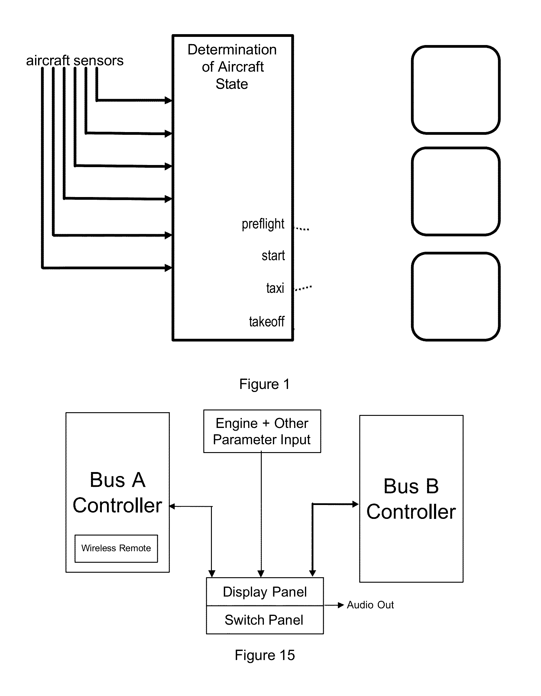
[0085]FIG. 15 is a schematic block diagram of an example embodiment of the present invention. A Display Panel accommodates communication of information to a pilot. A Switch Panel accommodates communication of information from a pilot. A single or dual redundant controller(s) can be used to determine state, to set controls, to control the display, to accept input in between the sensors and the display / switch. Sensors corresponding to various attributes of aircraft, such as those discussed above, provide information to the controller. The controller determines the state of the aircraft from the attributes, for example as described above. The controller sends information to the display which accepts input based on the determined state. For example, the controller can accept input from one or more switches, where the switches are defined to have specific meanings depending on the determined state. The controller initiates control of various aircraft attributes, for example those describ...


PUM


Abstract

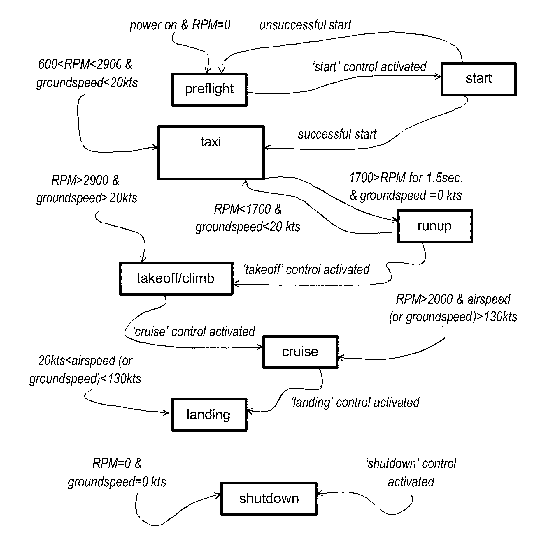
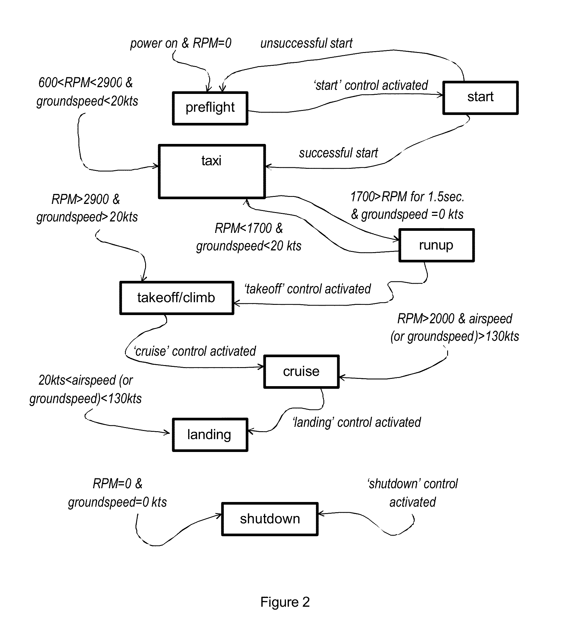
The present invention comprises methods and apparatuses for sensing attributes of an aircraft and efficiently communicating relevant attributes to a pilot. The invention allows a state of the aircraft to be determined, and then used to control systems, configure displays, select checklists relevant to the determined state, and automatically respond to emergencies based on the aircraft state. Embodiments of the invention can use the determined state of the aircraft to monitor and control electrical sensors and system as appropriate for the determined state; to communication information relevant to the determined state to a pilot (e.g., by displaying gauges in a manner and priority specific to the determined state); and to display contextually-relevant checklists (e.g., displaying a checklist of actions necessary for an aircraft in the determined state).

Description

BACKGROUND AND CROSS-REFERENCE TO RELATED APPLICATIONS[0001]The present invention is a continuation of U.S. Ser. No. 11 / 311,060, filed Dec. 19, 2005, which application is incorporated herein by reference. The present invention relates to avionics. Modern commercial / private aircraft, as well as older aircraft, include a myriad of instrumentation panels associated with electronic devices having controls, displays, and software applications, which are used to present information to pilots and / or copilots during flight. The electronic devices, controls, displays and applications are interfaced together to form avionics equipment within the aircraft. Pilots (where “pilot” includes copilots and any other controller of the aircraft) access one or more interface devices of the avionics equipment prior to and during the flight. Some of this information presented monitors the status of equipment on the aircraft, while other switches and knobs are used to control functions of the aircraft such...

Claims


Application Information

Patent Timeline
Patent Type & Authority Applications(United States)
IPC IPC(8): B64C19/00B64D45/00
CPCB64D45/00B64C19/00G01D7/00G01C23/00G01D2207/10
Inventor AUSMAN, MARCDOSTAL, JACOBCHURCH, ADAM
Owner ASTRONICS ADVANCED ELECTRONICS SYST
Learn More