Image forming apparatus

a technology of forming apparatus and forming tube, which is applied in the direction of digital output to print units, instruments, electrographic processes, etc., to achieve the effect of satisfying communication performance and usability

Active Publication Date: 2014-05-29
CANON KK
View PDF1 Cites 15 Cited by
  • Summary
  • Abstract
  • Description
  • Claims
  • Application Information

AI Technical Summary

Benefits of technology

[0007]The present disclosure provides appropriately arranging a communication portion for use in establishing near field communication in an image forming apparatus while at the same time achieving satisfactory communication performance and usability.

Problems solved by technology

However, Japanese Patent Laid-Open No. 2006-53477 does not disclose an appropriate location and orientation of the communication portion in the case where the communication portion is used in, so-called near field communication (NFC), which is a communication with a relatively short distance over which data is capable of being wirelessly communicated and where it is possible for the first time to establish communication by a user passing an information device that is to communicate with the image forming apparatus over a location that faces the communication portion of the image forming apparatus.

Method used


Image

  • Image forming apparatus
  • Image forming apparatus
  • Image forming apparatus

Examples


first embodiment

[0027]An embodiment of the present invention is described below. In the following description, when there is a plurality of devices having substantially the same configuration, such as photosensitive drums 10a, 10b, 10c, and 10d, they are indicated as a representative, such as a photosensitive drum 10, in describing the configuration and operations for the sake of simplification.

[0028][Image Forming Portion]

[0029]First, an image forming portion in the image forming apparatus is described. FIG. 3 is a schematic cross-sectional view of an image forming apparatus S. The image forming apparatus S is an electrophotographic tandem laser beam printer and can form a four-color image on a sheet recording medium, such as paper or OHP film.

[0030]The configuration of the image forming portion is described below. The image forming portion includes a drum-type electrophotographic photosensitive member (hereinafter referred to as “photosensitive drum”) 10 (10a to 10d) for each color. The photosens...

second embodiment

[0070]A second embodiment is described next. The same reference numerals are used in the configuration substantially the same as that in the first embodiment, and the detailed description thereof is omitted.

[0071][Arrangement of Communication Portion 31]

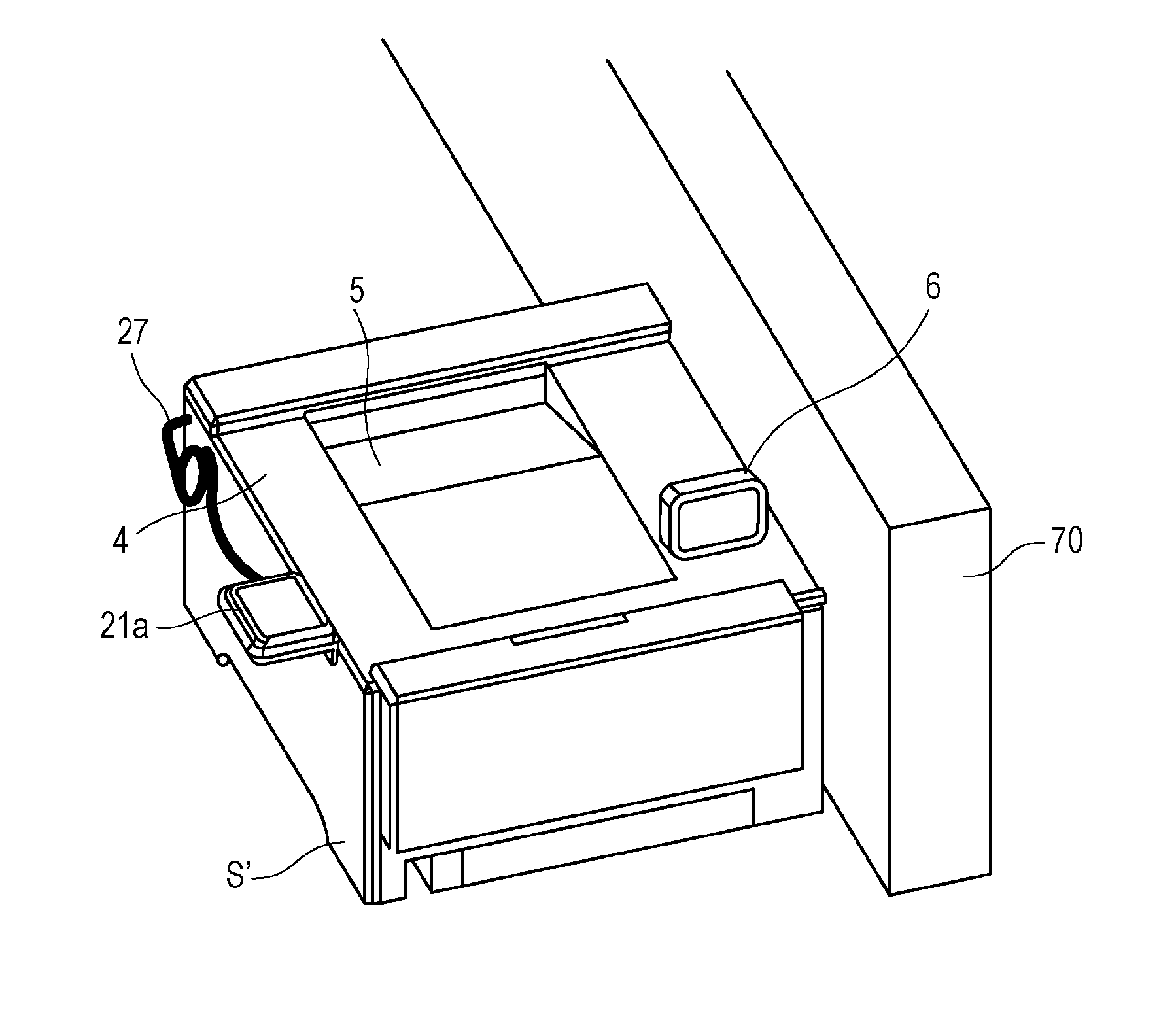
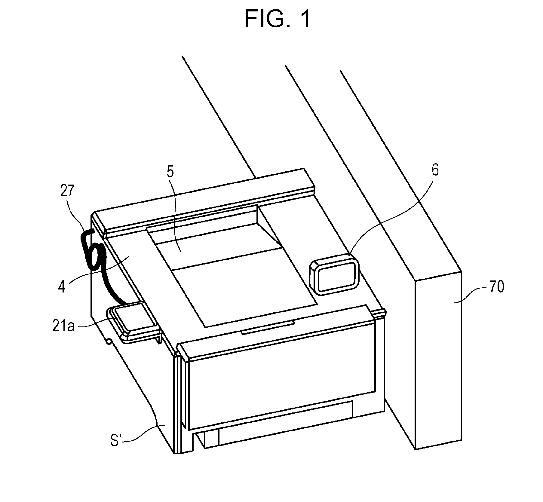
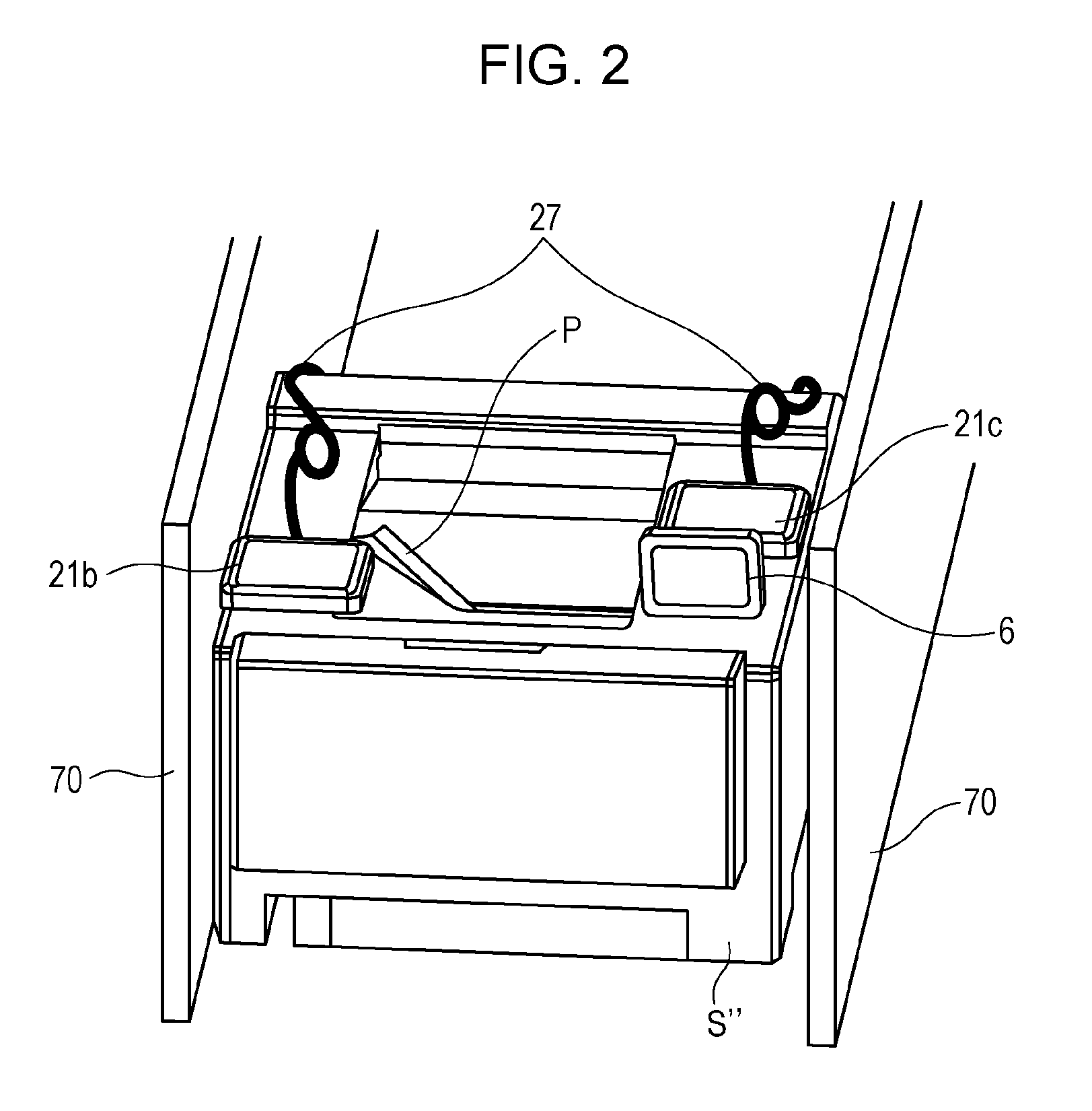
[0072]FIG. 8A is a perspective view of the image forming apparatus S. FIG. 8B illustrates the image forming apparatus S in FIG. 8A when the cover 4 is assumed to be transparent. FIG. 9A is a top view of the image forming apparatus S. FIG. 9B illustrates the image forming apparatus S in FIG. 9A when the cover 4 is assumed to be transparent. In the present embodiment, an image reading portion 7 configured to read an image on an original is supported above the upper section of the cover 4, the operation panel 6 is supported on the left side as seen from the front of the apparatus, and the communication portion 31 is disposed on the inner side of the upper section of the cover 4 on the right side as seen from the front of apparatus. The ...


PUM


Abstract

An image forming apparatus includes a communication portion arranged inside a cover covering an image forming portion in the main body of the apparatus and including an antenna surface for use in establishing near field communication. The cover includes a stacking portion in its upper section. The stacking portion is configured to receive a recording medium with an image thereon, the recording medium being discharged outside the main body of the apparatus. The antenna surface faces a region of the upper section of the cover downstream in a direction of discharging the recording medium. The antenna surface at least partially faces a region of the upper section of the cover outside the stacking portion in a direction perpendicular to the direction of discharging the recording medium. The communication portion is capable of communicating with another communication portion using near field communication.

Description

BACKGROUND OF THE INVENTION[0001]1. Field of the Invention[0002]The present invention relates to an image forming apparatus, such as a laser beam printer or a copier, for forming an image on a recording medium.[0003]2. Description of the Related Art[0004]There is an image forming apparatus capable of receiving image data to be printed from an information device, such as a personal computer or a cellular phone, using wireless communication and of forming an image based on the image data. Such an image forming apparatus includes a communication portion for establishing wireless communication.[0005]Japanese Patent Laid-Open No. 2006-53477 describes arrangement of a reception portion (communication portion) for wireless communication in the main body of an image forming apparatus.[0006]However, Japanese Patent Laid-Open No. 2006-53477 does not disclose an appropriate location and orientation of the communication portion in the case where the communication portion is used in, so-called n...

Claims


Application Information

Patent Timeline
Patent Type & Authority Applications(United States)
IPC IPC(8): H04N1/00H04B5/00
CPCH04N1/00315H04N1/00103H04B5/0031G03G21/1657G03G15/5087H04N2201/006H04N1/00127H04N2201/0081H04N2201/0082H04N1/04H04N2201/0055
Inventor YUZAWA, ATSUYUKI
Owner CANON KK
Why Eureka
Try Eureka