Antenna device and mobile communication terminal

a mobile communication terminal and antenna device technology, applied in the direction of differential interacting antenna combinations, instruments, protective materials radiating elements, etc., can solve the problems of limited approach and affect the communication performance of the antenna device disposed in the casing, such as the ic card, so as to improve the gain of transmit and receive signals, increase the communication distance, and improve the effect of transmitting and receiving signals

Active Publication Date: 2012-07-12
MURATA MFG CO LTD
View PDF6 Cites 36 Cited by
  • Summary
  • Abstract
  • Description
  • Claims
  • Application Information

AI Technical Summary

Benefits of technology

[0012]The emitting member includes the opening portion provided in the portion thereof and the slit portion communicating with the opening portion, and, when seen in plan view from the direction of the winding axis of the coil pattern, the opening portion of the emitting member and the inner region of the coil pattern overlap each other at least partially and the emitting member and the coil pattern overlap each other at least partially. Therefore, when a current passes through the coil pattern, an excited magnetic field passes through the opening portion of the emitting member and is ideally distributed, and the induction field excites an inductive current in the vicinity of the opening portion of the emitting member. This can improve the gain of transmit and receive signals and increase the communication distance.
[0013]According to various preferred embodiments of the present invention, the gain of transmit and receive signals can be improved, and satisfactory communication performance is achieved.

Problems solved by technology

However, a mobile communication terminal, such as a cellular phone, is small and multifunctional, so various metallic components are disposed in a small casing with high density.
Accordingly, there is an issue in that the communication performance of an antenna device disposed in a casing, such as an IC card, is affected by a metallic component in the casing.
However, such an approach is limited under the present circumstances.

Method used


Image

  • Antenna device and mobile communication terminal
  • Antenna device and mobile communication terminal
  • Antenna device and mobile communication terminal

Examples


first preferred embodiment

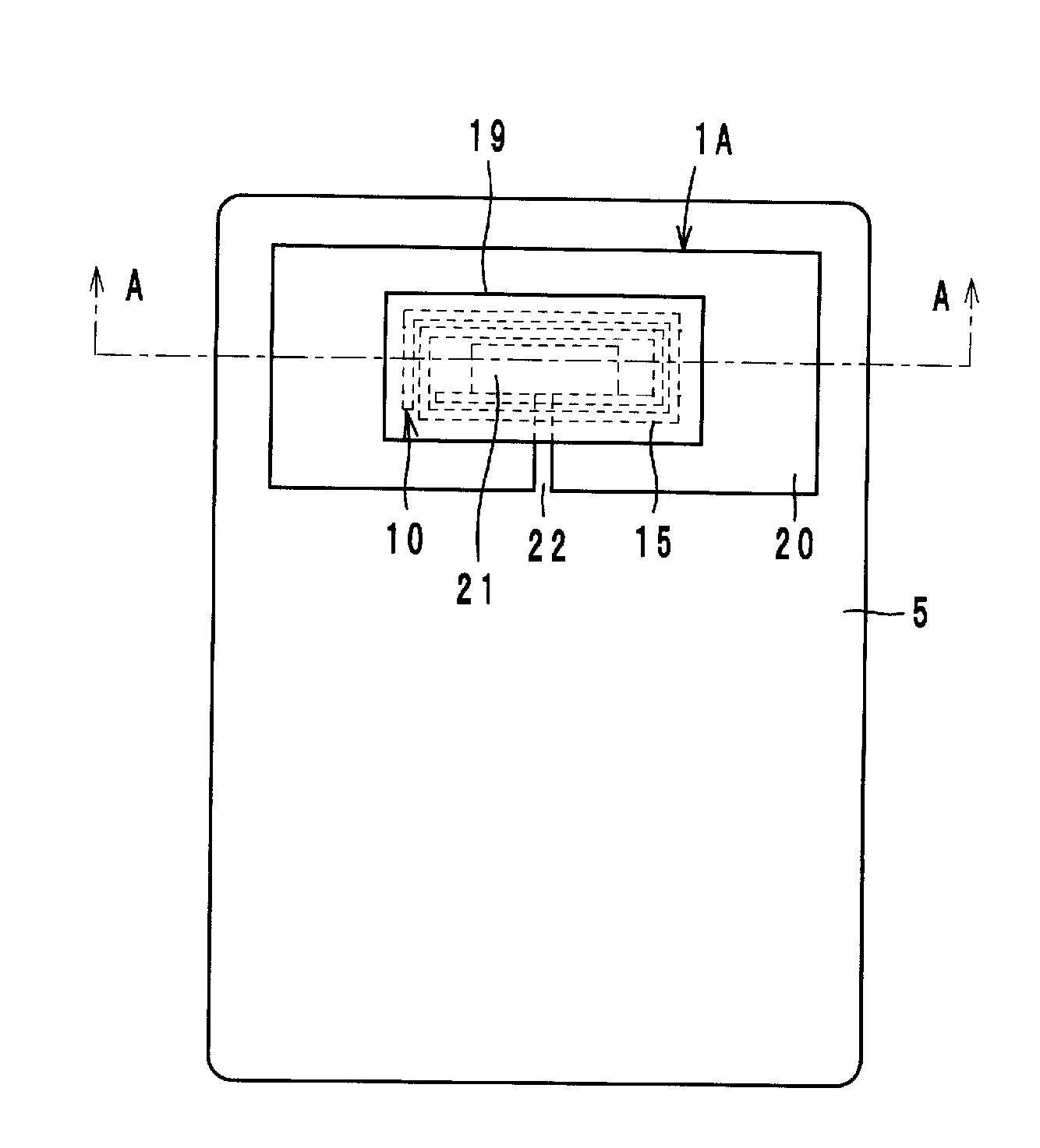
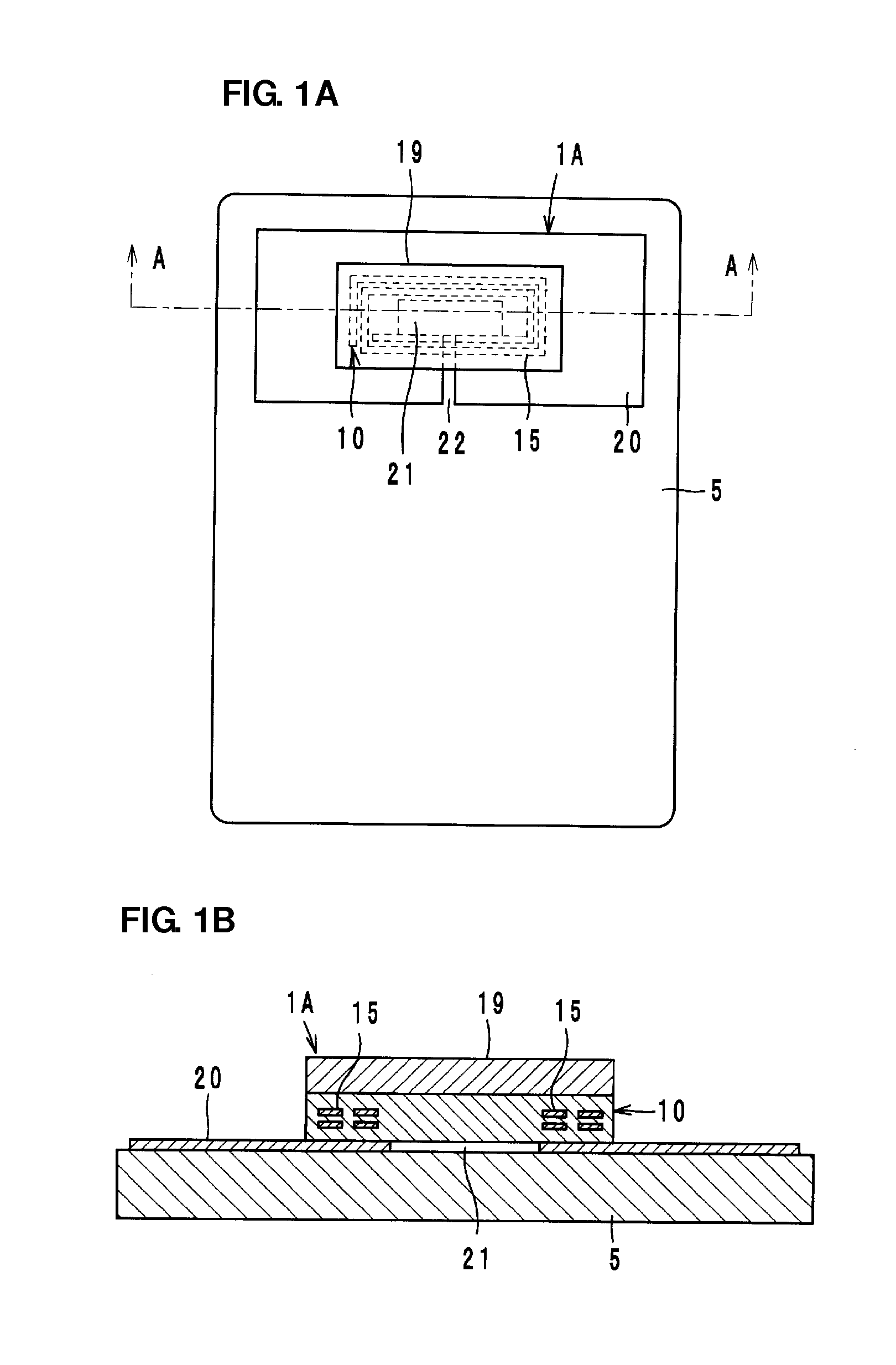
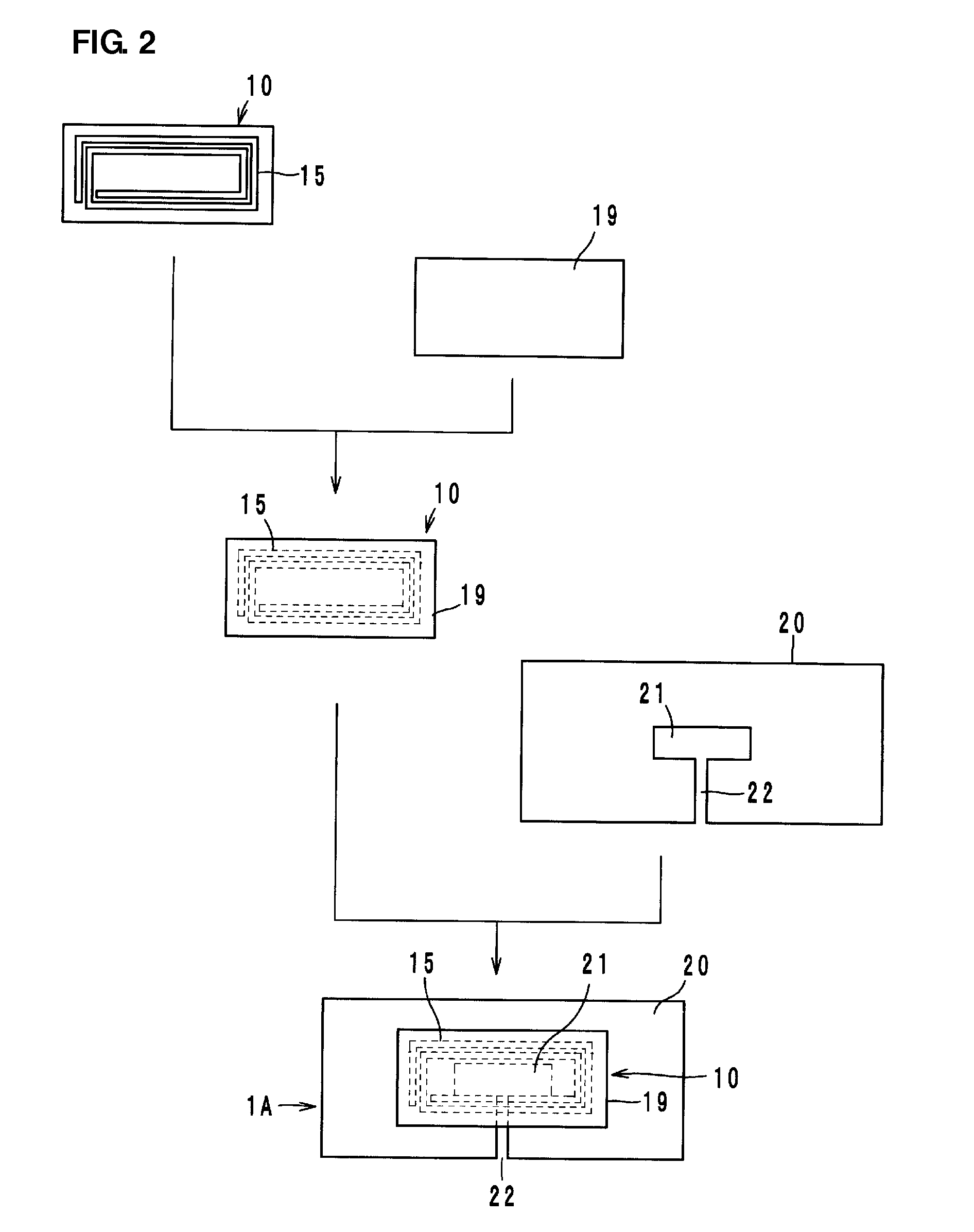
[0031]An antenna device 1A, which is a first preferred embodiment, includes a feeding member 10 on the back side of a casing 5 of a mobile communication terminal (e.g., a cellular phone), a magnetic member 19 made of a ferrite sheet attached to the feeding member 10, and an emitting member 20, the feeding member 10 containing a coil pattern 15, as illustrated in FIGS. 1A and 1B.

[0032]The emitting member 20 defines an antenna to emit a signal supplied from the feeding member 10 and to receive a receive signal and supply it to the feeding member 10. The emitting member 20 is provided on the back side of the casing 5 and includes a metallic film or foil. The feeding member 10 includes a stack in which a plurality of dielectric layers (preferably made of thermoplastic resin sheets, for example) are stacked on each other. The coil pattern 15 is a coil in which a plurality of ring-shaped conductors arranged on the plurality of dielectric layers are helically connected to each other with a...

second preferred embodiment

[0058]An antenna device 1B, which is a second preferred embodiment, preferably has basically the same configuration as that of the antenna device 1A, which is the first preferred embodiment, and differs in that a conductor member (hereinafter referred to as ground conductor 7) disposed on a printed wiring board 6 mounted on a mobile communication terminal and the emitting member 20 are coupled to each other through a capacitance C (see FIG. 9), as illustrated in FIGS. 8A and 8B. More specifically, the ground conductor 7 and the emitting member 20 are opposed to each other, a dielectric layer 18, which is an adhesive, is positioned between the emitting member and a conductive member (capacitance assisting element) 8 electrically connected to the ground conductor 7. Thus, the capacitance C is generated between the conductive member 8 and the emitting member 20.

[0059]The operational advantage of the antenna device 1B, which is the second preferred embodiment, is basically the same as t...

seventh preferred embodiment

[0068]An antenna device 1G, which is a seventh preferred embodiment, is the one in which two conductive members (capacitance assisting elements) 8 electrically connected to the ground conductor 7 are disposed and two capacitances C1 and C2 are generated between the conductive members 8 and the emitting member 20. The antenna device 1G is an application of the antenna device 1B, which is described in the above-described second preferred embodiment, and can efficiently feed the eddy-current energy consumed in the ground conductor 7 back to the emitting member 20. In particular, for the antenna device 1G, because conductive members 8 are arranged on both sides of the slit portion 22, respectively, the feedback of the eddy-current energy is efficient. The feedback of the eddy-current energy used here indicates that the ground conductor 7 is enabled to be used as a part of the emitting portion by the formation of a single resonant circuit containing the slit portion 22, the ground conduc...


PUM


Abstract

An antenna device includes a feeding member including a coil pattern and an emitting member to emit a transmit signal supplied from the feeding member and to receive a receive signal and supplying it to the feeding member. The emitting member includes an opening portion and a slit portion communicating with the opening portion. When seen in plan view from the direction of the winding axis of the coil pattern, the opening portion of the emitting member and the inner region of the coil pattern overlap each other, and the emitting member and the coil pattern overlap each other at least partially.

Description

BACKGROUND OF THE INVENTION[0001]1. Field of the Invention[0002]The present invention relates to an antenna device and a mobile communication terminal, and in particular, to an antenna device for use in a radio frequency identification (RFID) system or the like and a mobile communication terminal that includes the antenna device.[0003]2. Description of the Related Art[0004]In recent years, an RFID system, in which predetermined information and electric power are transmitted and received by non-contact communication using an electromagnetic field between a reader-writer for generating an induction field and a wireless IC device that is attached to an object and that stores the predetermined information, such as an IC tag, has been developed as a management system for objects and information.[0005]For example, Japanese Unexamined Patent Application Publication No. 2003-37861 discloses a cellular phone in which a non-contact IC card is embedded. However, a mobile communication terminal...

Claims


Application Information

Patent Timeline
Patent Type & Authority Applications(United States)
IPC IPC(8): H01Q13/10
CPCG06K19/07749G06K19/07756G06K19/07786H04B5/0025H01Q1/40H01Q7/00H01Q13/10H01Q1/2225H01Q1/2216H01Q1/243H01Q9/16H01Q21/29G06K19/077H01Q1/24H01Q1/38
Inventor KATO, NOBORUSASAKI, JUNMIURA, TEPPEI
Owner MURATA MFG CO LTD
Why Eureka
Try Eureka