Heat dissipating fan

Inactive Publication Date: 2014-05-29
COOLER MASTER CO LTD
View PDF3 Cites 2 Cited by
  • Summary
  • Abstract
  • Description
  • Claims
  • Application Information

AI Technical Summary

Benefits of technology

[0008]As mentioned in the above, the invention disposes the magnetic member in the ring-shaped casing and utilizes the at least one protruding portion, which protrudes from one side of the ring-shaped casing inwardly, to hold the magnetic member. Furthermore, when the axle of the rotor is inserted into the bearing

Problems solved by technology

However, the quality of the anaerobic adhesive may degrade easily after being used for a long time or under high temperature such that the magnetic member 142 may come off the fan wheel 140.
Accordingly, the heat dissipating fan may have a break

Method used


Image

  • Heat dissipating fan
  • Heat dissipating fan
  • Heat dissipating fan

Examples


Embodiment Construction

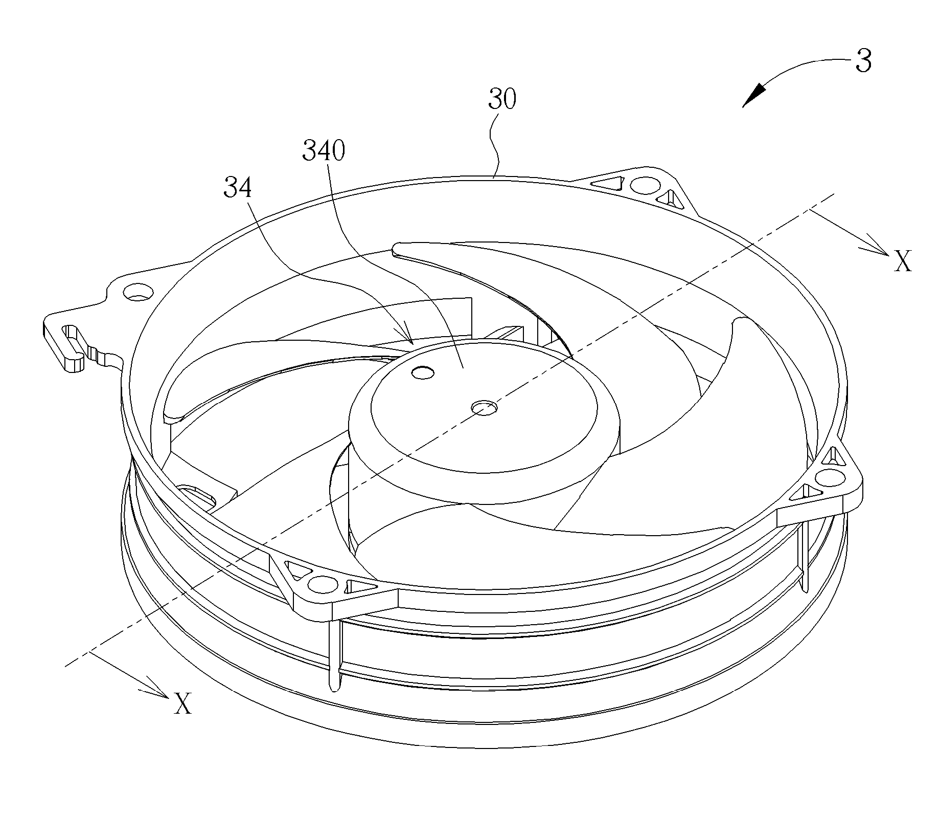
[0017]Referring to FIGS. 3 to 7, FIG. 3 is a perspective view illustrating a heat dissipating fan 3 according to an embodiment of the invention, FIG. 4 is an exploded view illustrating the heat dissipating fan 3 shown in FIG. 3, FIG. 5 is an exploded view illustrating the heat dissipating fan 3 shown in FIG. 3 from another viewing angle, FIG. 6 is a cross-sectional view illustrating the heat dissipating fan 3 shown in FIG. 3 along line X-X, and FIG. 7 is a bottom view illustrating the winding structure 322, the ring-shaped casing 342 and the magnetic member 344 shown in FIG. 6.

[0018]As shown in FIGS. 3 to 6, the heat dissipating fan 3 comprises a fan frame 30, a stator 32 and a rotor 34, wherein the stator 32 and the rotor 34 are disposed in the fan frame 30. The stator 32 comprises a bearing 320 and a winding structure 322, wherein the bearing 320 is disposed in the winding structure 322. In this embodiment, the winding structure 322 has a plurality of teeth 324 and there is a gap ...


PUM


Abstract

A heat dissipating fan includes a stator and a rotor. The stator includes a bearing and a winding structure, wherein the bearing is disposed in the winding structure. The rotor includes a fan wheel, a ring-shaped casing and a magnetic member, wherein the ring-shaped casing is disposed in the fan wheel and the magnetic member is disposed in the ring-shaped casing. The fan wheel has an axle inserted into the bearing such that the winding structure is located within the magnetic member. At least one protruding portion protrudes from one side of the ring-shaped casing inwardly and is extended below the winding structure so as to hold the magnetic member and interfere with the winding structure.

Description

BACKGROUND OF THE INVENTION[0001]1. Field of the Invention[0002]The invention relates to a heat dissipating fan and, more particularly, to a heat dissipating fan capable of holding a magnetic member stably and preventing a rotor from coming off a stator effectively.[0003]2. Description of the Prior Art[0004]Referring to FIG. 1, FIG. 1 is a cross-sectional view illustrating a heat dissipating fan 1 of the prior art. As show in FIG. 1, the heat dissipating fan 1 comprises a fan frame 10, a stator 12 and a rotor 14, wherein the stator 12 and the rotor 14 are disposed in the fan frame 10. The stator 12 comprises a bearing 120, a plurality of teeth 122 and a plurality of coils 124, wherein the teeth 122 are disposed around the bearing 120 and the coils 124 are wound around the teeth 122. The rotor 14 comprises a fan wheel 140 and a magnetic member 142, wherein the magnetic member 142 is attached on an inner wall of the fan wheel 140 and the fan wheel 140 has an axle 144 inserted into the...

Claims


Application Information

Patent Timeline
IPC IPC(8): F04D19/00
CPCF04D19/00F04D25/064F04D19/002F04D25/0646
Inventor HU, KAI-HSIANGXU, SHIMANLAI, JIASHENGHE, HAIJUN
Owner COOLER MASTER CO LTD
Why Eureka
Try Eureka