Water Conveying Device

Inactive Publication Date: 2014-06-05
ZHADANOV ELI +1
View PDF5 Cites 0 Cited by
  • Summary
  • Abstract
  • Description
  • Claims
  • Application Information

AI Technical Summary

Benefits of technology

The present invention provides a device for conveying water that avoids the disadvantages of prior art devices. The device has two water conveying members with channels and holes that allow water to flow successively from one member to the other. The device also has fixing means that hold the members together, lock them in a specific position, and press the seals to ensure a leak-free operation. The technical effects of this invention are improved water conveyance with reduced risks of leaks and other technical disadvantages.

Problems solved by technology

When the device is designed as in the above mentioned prior art, the first and second water supplying members connected by the device are offset sideways from one another, occupy more space, and create imbalance.

Method used


Image

  • Water Conveying Device
  • Water Conveying Device
  • Water Conveying Device

Examples


Embodiment Construction

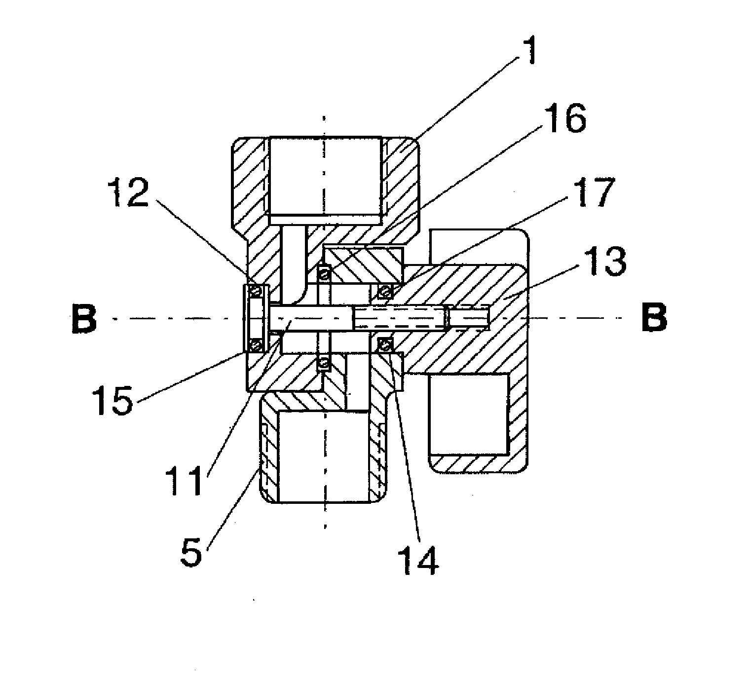
[0028]A water conveying system in accordance with the present invention has two hollow water conveying members through which water can flow from a first water supplying element, for example a fixedly mounted water supplying pipe, to a second water supplying element, for example a showerhead, and which are turnable relative to one another about a turning axis, for example to change an orientation of the second water supplying member and / or a water flow direction water from the latter.

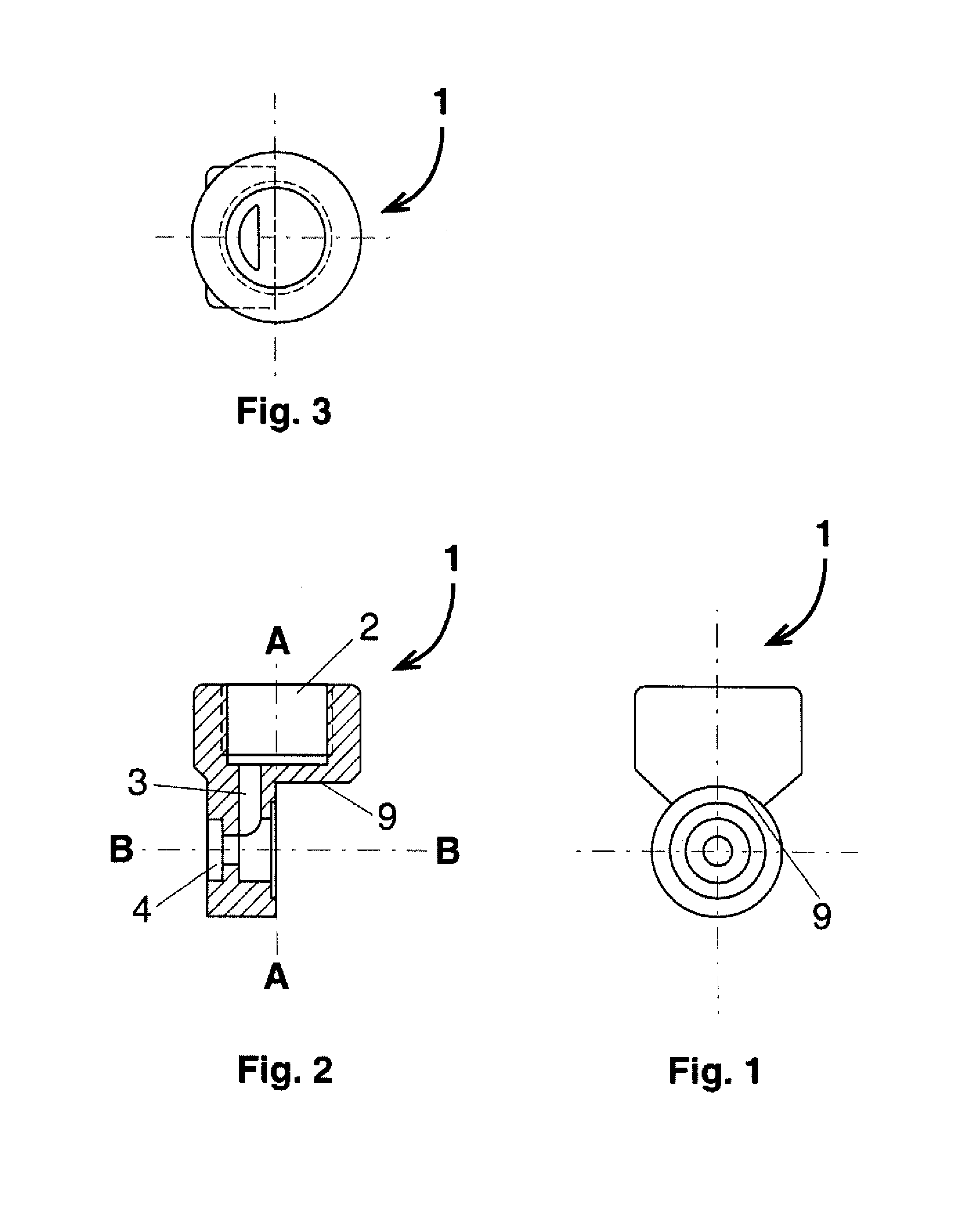
[0029]The first water conveying member is identified with reference numeral 1. It has a first opening 2 forming an inlet and having a first axis A-A, a channel 3 extending from the first opening 2 and having an axis parallel to the axis A-A, and a through hole 4 extending from the channel 3 along a turning axis B-B which is perpendicular to the axis A-A. The opening 2 is used for insertion of a first water supplying element and is provided with first connecting means formed as an inner thread engageable ...


PUM


Abstract

A device for conveying water between first and second water supplying elements has a first hollow water conveying member connectable to the first water supplying element and a second hollow water conveying member connectable to the second water supplying element and with the first water conveying members are turnable relative to one another and about a turning axis, and the first water conveying member has a first opening for water entry and the second water conveying member has a second opening for water exit, and the openings extend transversely to the turning axis and are coaxial with each other.

Description

BACKGROUND OF THE INVENTION[0001]The present invention relates to water conveying devices for connecting two water supplying members, for example a first hollow water supplying member such as a wall-mounted pipe, with a second hollow water supplying member such as a fixed-mounted showerhead, a hand-held showerhead and the like.[0002]The above mentioned water conveying devices usually include a first water supplying member connectable to a wall-mounted fixed pipe, and a second water supplying member connectable with a showerhead, wherein the first water supplying member has an inlet opening and the second water-supplying member has an outlet opening, and the first and second members are turnable relative to one another, so that the outlet opening of the second water supplying member upon its turning can be located at any desirable location.[0003]Devices for conveying water of the above mentioned general type are known in the art and widely used in shower rooms, bathrooms, etc. In the...

Claims


Application Information

Patent Timeline
IPC IPC(8): F17D1/00
CPCF16L27/0849B05B1/18B05B15/652Y10T137/598
Inventor ZHADANOV, ELIZHADANOV, SAM
Owner ZHADANOV ELI
Why Eureka
Try Eureka