Arc Chute Arrangement for Arc Quenching in Electrical Switching Device

a technology of electrical switching device and arc chute, which is applied in the direction of air-break switch, high-tension/heavy-dress switch, electrical apparatus, etc., can solve the problems of arc flashing over or restriking, reducing the effectiveness of arc,

Active Publication Date: 2014-06-05
SCHNEIDER ELECTRIC INDIA
View PDF13 Cites 3 Cited by
  • Summary
  • Abstract
  • Description
  • Claims
  • Application Information

AI Technical Summary

Benefits of technology

[0017]Yet another object of the present invention i...

Problems solved by technology

This current path formed due to molten material reduces the effecti...

Method used


Image

  • Arc Chute Arrangement for Arc Quenching in Electrical Switching Device
  • Arc Chute Arrangement for Arc Quenching in Electrical Switching Device
  • Arc Chute Arrangement for Arc Quenching in Electrical Switching Device

Examples


Embodiment Construction

presented later.

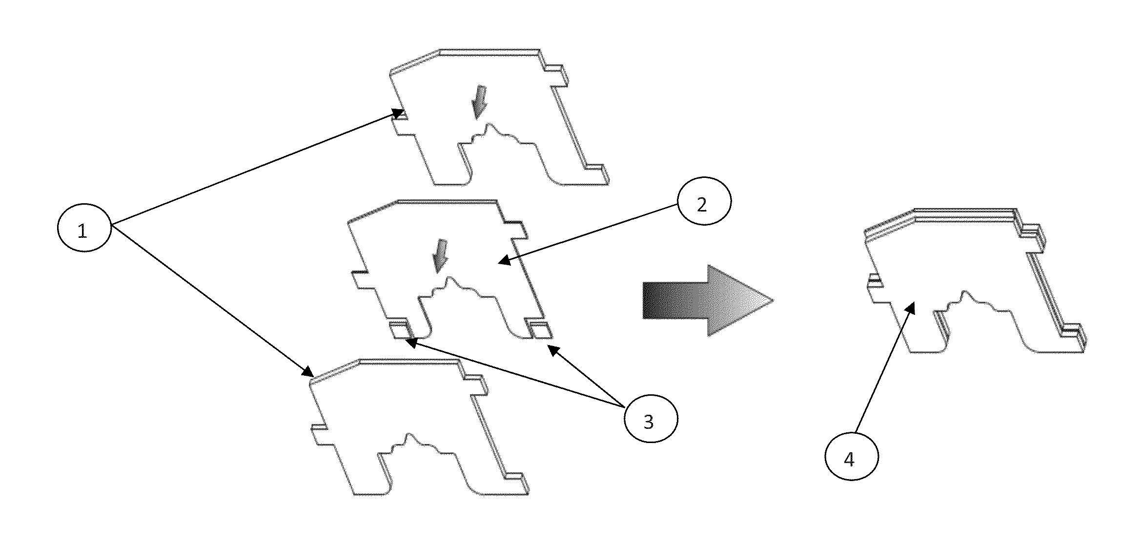
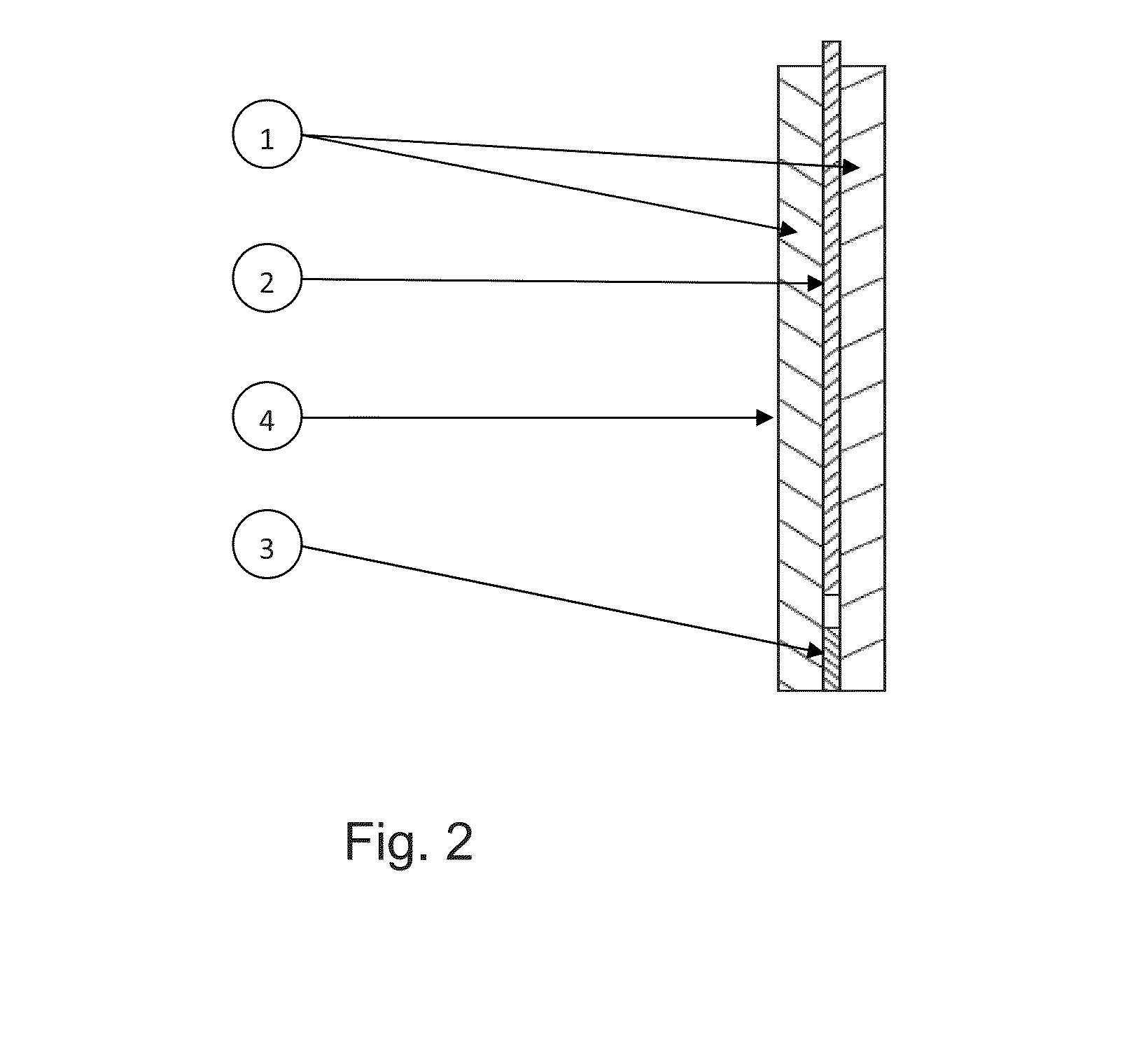
[0020]There is provided arc chute arrangement for arc quenching in electrical switching device.

[0021]According to one aspect of the present invention, there is provided arc chute arrangement for arc quenching in electrical switching device, said arrangement comprising a plurality of deion plates, each said deioni plates further comprising a pair of plates, electrically connected to each other, having an ablative material sandwiched there between; a lining means for holding said deion plates; wherein said deion plates having a chamfered profile at one corner to minimize the possibility of flash-over arc restrike and to generate high magnetic field that drive the arc inside arc chute and said chamfered profile arranged alternatively thereby substantially lengthening the arc.

[0022]Other aspects, advantages, and salient features of the invention will become apparent to those skilled in the art from the following detailed description, which, taken in conjunction with the ...


PUM


Abstract

An arc chute arrangement for arc quenching in electrical switching device, said arrangement comprising a plurality of deion plates, each said deion plates further comprising a pair of plates having an ablative material sandwiched therebetween; a lining means for holding said deion plates; wherein said deion plates having a chamfered profile at one corner to generate high magnetic field that drive the arc inside arc chute and said chamfered profile arranged alternatively thereby substantially lengthening the arc.

Description

BACKGROUND OF THE INVENTION[0001]1. Field of the Invention[0002]The present invention relates generally to electrical switching devices. More particularly the invention relates to an arc chute arrangement for arc quenching in electrical switching devices.[0003]2. Description of Related Art[0004]Conventional Circuit Breaker consists of housing and cover made up of insulating material, pair of separable contacts enclosed within the housing, cover and arc quenching device known as Arc chute. The switching arc in circuit breaker and its motion are determined by the intensity of current, electromagnetic from arc chute as well as the gas-dynamic process within the arc chute.[0005]The arc chute consists of stack of deion plates made up of magnetic material to attract, split-up & cool the arcs. The stack of deion plates is trapped in between two plates known as lining made up of electrically insulating material. The function of deion plates is to split the arc in several series arcs of appr...

Claims


Application Information

Patent Timeline
IPC IPC(8): H01H33/10
CPCH01H9/302H01H9/341H01H9/345H01H9/362H01H2009/365H01H2009/367
Inventor NAHATA, DEEPAKROY, JIBANESHOCHANI, DEEPAK M.
Owner SCHNEIDER ELECTRIC INDIA
Why Eureka
Try Eureka