Decomposition and mitigation of a disturbance being present at an electric connection between an electric power generating system and a power grid

a technology of electric power generation system and disturbance, applied in the direction of noise figure or signal-to-noise ratio measurement, instruments, power supply testing, etc., can solve the problems of disturbance, disturbance, disturbance, etc., and achieve the effect of reducing the probability of disturban

Active Publication Date: 2014-06-05
SIEMENS AG
View PDF3 Cites 11 Cited by
  • Summary
  • Abstract
  • Description
  • Claims
  • Application Information

AI Technical Summary

Benefits of technology

[0025]Generally speaking, the described method allows for a separation between (a) the individual complex harmonic currents I1(n) generated by the electric power generating system or any power electronic device being assigned to the electric power generating system and (b) the individual complex harmonic currents I2(n) caused by the back ground harmonics present at the electric connection between an electric power generating system and a power grid. In this way a more accurate electric model representation of the electric power generating system can be formed at each harmonic frequency.
[0028]According to a further embodiment of the invention first disturbances are caused by a power converter of the electric power generating system. This may provide the advantage that with the described method a notably strong source of electric disturbances at an electric connection between the electric power generating system and the power grid can be examined.
[0033]Therein, Upwm(n) is the disturbing voltage and the open circuit voltage, Um(n) is the measured voltage value, Im(n) is the measured current value, Zchm(n) is characteristic equivalent impedance of the electric power converter system and n is a parameter value being indicative for the frequency component, at which the strength of the first disturbance is determined. This may provide the advantage that the (strength of the) voltage component of the first disturbance can be determined in an easy and reliable manner.
[0036]Using the predefined impedance value Zgrid_f(n), which may represent the impedance of a fictitious grid, may provide the advantage that for analyzing the first disturbance special characteristics of the grid, the electric power generating system is actually connected to, can be eliminated. Thereby, harmonic current emissions from different individual electric power generating systems can be directly compared with each other.
[0038]The described method is based on the idea that by determining the first disturbance level being assigned to the electric power generating system independently from the second disturbance level being assigned to the power grid, the overall disturbance level at the electric connection between the electric power generating system and the power grid can be significantly reduced by operating the electric power generating system in response to the determined strength of the first disturbance.
[0044]It is pointed out that the described data processing unit can also be used for mitigating a disturbance on an electric signal being present at an electric connection between an electric power generating system and a power grid. In order to achieve this, the data processing unit is, if applicable together with a control unit for controlling the operation of the electric power generating system, adapted for controlling the above described disturbance mitigation method. In this case the described data processing unit is based on the idea that by determining the first disturbance level being assigned to the electric power generating system independently from the second disturbance level being assigned to the power grid, the overall disturbance level at the electric connection between the electric power generating system and the power grid can be significantly reduced by operating the electric power generating system in an appropriate manner in response to the determined strength of the first disturbance.

Problems solved by technology

However, in practice there always exist at least some disturbances on an electric signal being present at an electric power connection line between the wind turbine(s) and the power grid.
These disturbances are in particular harmonic disturbances, which may be caused for instance by the switching frequency of a PWM modulated power converter or of passive rectifier bridges, system resonances, arc furnaces .
However, disturbances are also caused by electric equipment being connected to the power grid.
It is mentioned that disturbances can also be caused by non-idealities in the power system itself, e.g. saturation in the power system transformers.
Therefore, power grid operators are required to ensure a reliable delivery of power with a quality that meets certain standards to ensure an untroubled operation of any type of electric equipment being connected to the power grid.
This holds in particular for the harmonic distortion caused by power converters or frequency converters.
However, it should be understood that of course all harmonics in the power grid are unwanted and might course problems in the system and / or in connected electric equipment.
However, where problems in connection with lower order harmonics are expected, it is known to use so called park level filters in order encounter such problems.
This assumption, which can be seen as a consequence of not taking into account the harmonic disturbances (background harmonics) which are already present in the power grid, has inter alia the drawback, that an active filtering cannot be incorporated in the power converter, because it is presently not possible to distinguish between harmonic disturbances caused by background harmonics within the power grid and harmonic disturbances caused by the power converter.

Method used


Image

  • Decomposition and mitigation of a disturbance being present at an electric connection between an electric power generating system and a power grid
  • Decomposition and mitigation of a disturbance being present at an electric connection between an electric power generating system and a power grid
  • Decomposition and mitigation of a disturbance being present at an electric connection between an electric power generating system and a power grid

Examples


Embodiment Construction

[0061]The illustration in the drawing is schematically. It is noted that in different figures, similar or identical elements are provided with the same reference signs or with reference signs, which are different from the corresponding reference signs only within the first digit.

[0062]The present invention is especially useful for wind turbine applications on wind turbine level and / or on wind farm level comprising a plurality of wind turbines. However, the present invention can also be used with other electric power setups such as the connection of a solar power plant or a wave energy power plant to a power grid, which plants have also spatially distributed power generating systems and, if applicable power converters respectively frequency converters for connecting the power generating systems to the power grid.

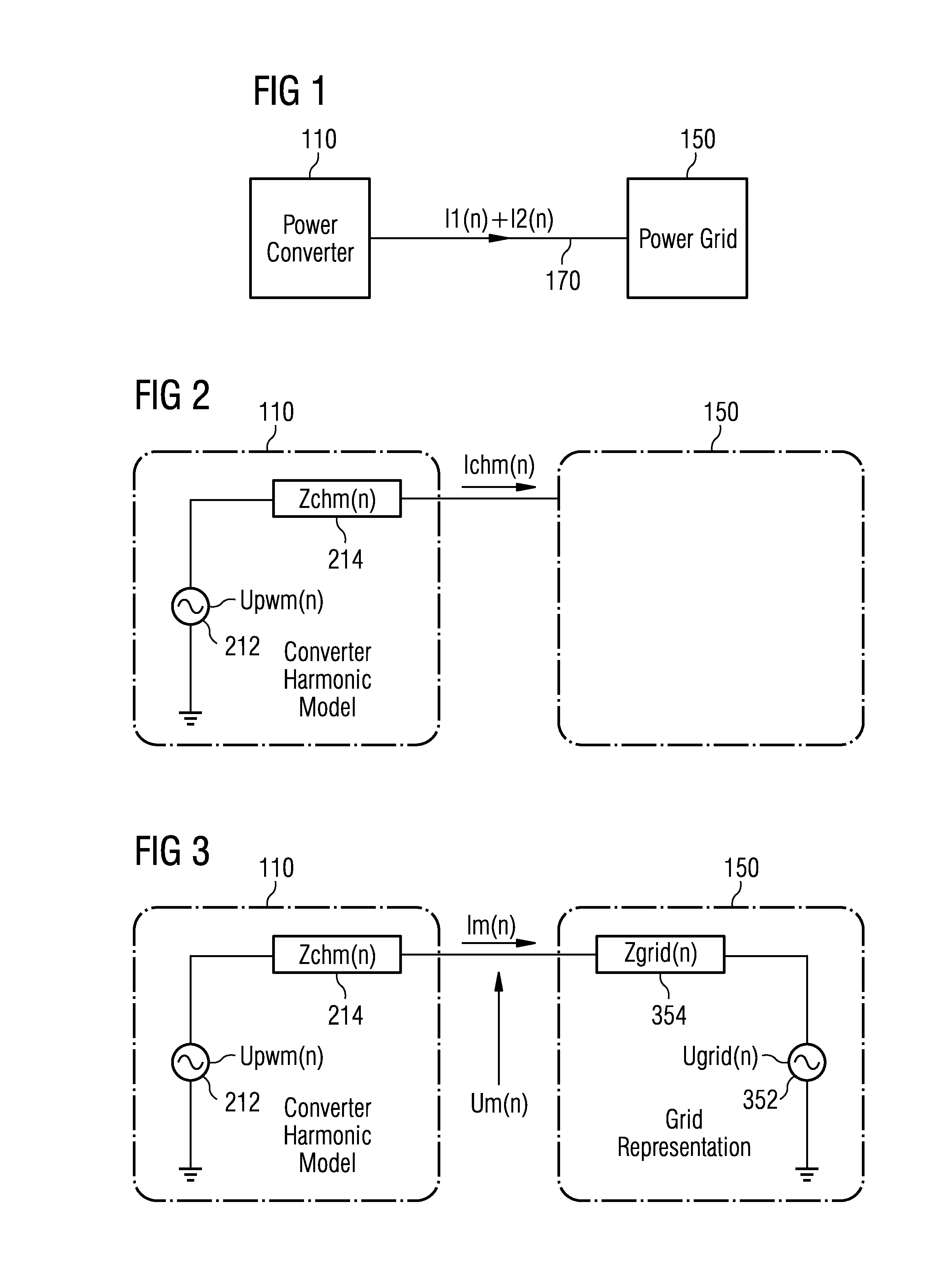
[0063]FIG. 1 schematically illustrates a decomposition of a disturbance current into (a) a first disturbance current I1(n) being assigned to a power converter 110 and into (b...


PUM


Abstract

A disturbance on an electric signal at an electric connection between an electric power generating system and a power grid is decomposed into a first disturbance with a first strength assigned to the electric power generating system and a second disturbance with a second strength assigned to the power grid. A voltage value of a voltage of the electric signal is measured. A current value of a current of the electric signal is measured. A value of an open circuit voltage of an equivalent voltage source is calculated based on the measured voltage value, the measured current value and a characteristic equivalent impedance of the electric power generating system so that the electric power generating system is in a harmonic model. The strength of the first disturbance is determined based on the calculated value of the open circuit voltage of the equivalent voltage source.

Description

FIELD OF INVENTION[0001]The present invention relates to the technical field of electrically connecting an electric power generating system, in particular a wind turbine or a wind farm comprising a plurality of wind turbines, with a power grid. In particular, the present invention relates to a method for decomposing a disturbance on an electric signal being present at an electric connection between an electric power generating system and a power grid into a first disturbance with a first strength, wherein the first disturbance is assigned to the electric power generating system, and a second disturbance with a second strength, wherein the second disturbance is assigned to the power grid. Further, the present invention relates to a method for mitigating such a disturbance. Furthermore, the present invention relates to a data processing unit, to an electric power generating system and to a computer program, which are all adapted for controlling the above mentioned methods.ART BACKGROU...

Claims


Application Information

Patent Timeline
Patent Type & Authority Applications(United States)
IPC IPC(8): H02M1/12G01R19/00
CPCG01R19/00H02M1/12G01R23/20G01R31/40H02S50/00Y02E10/50G01R29/0814G01R29/26
Inventor ANDRESEN, BJORNBROGAN, PAUL BRIANGOLDENBAUM, NIKOLAUS MOELLER
Owner SIEMENS AG
Why Eureka
Try Eureka