Electrical connector
- Summary
- Abstract
- Description
- Claims
- Application Information
AI Technical Summary
Benefits of technology
Problems solved by technology
Method used
Image

Examples
Embodiment Construction
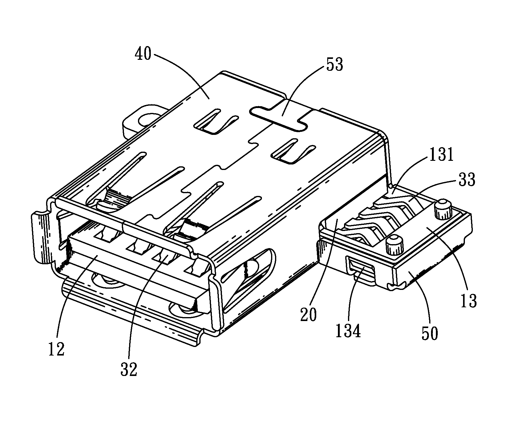
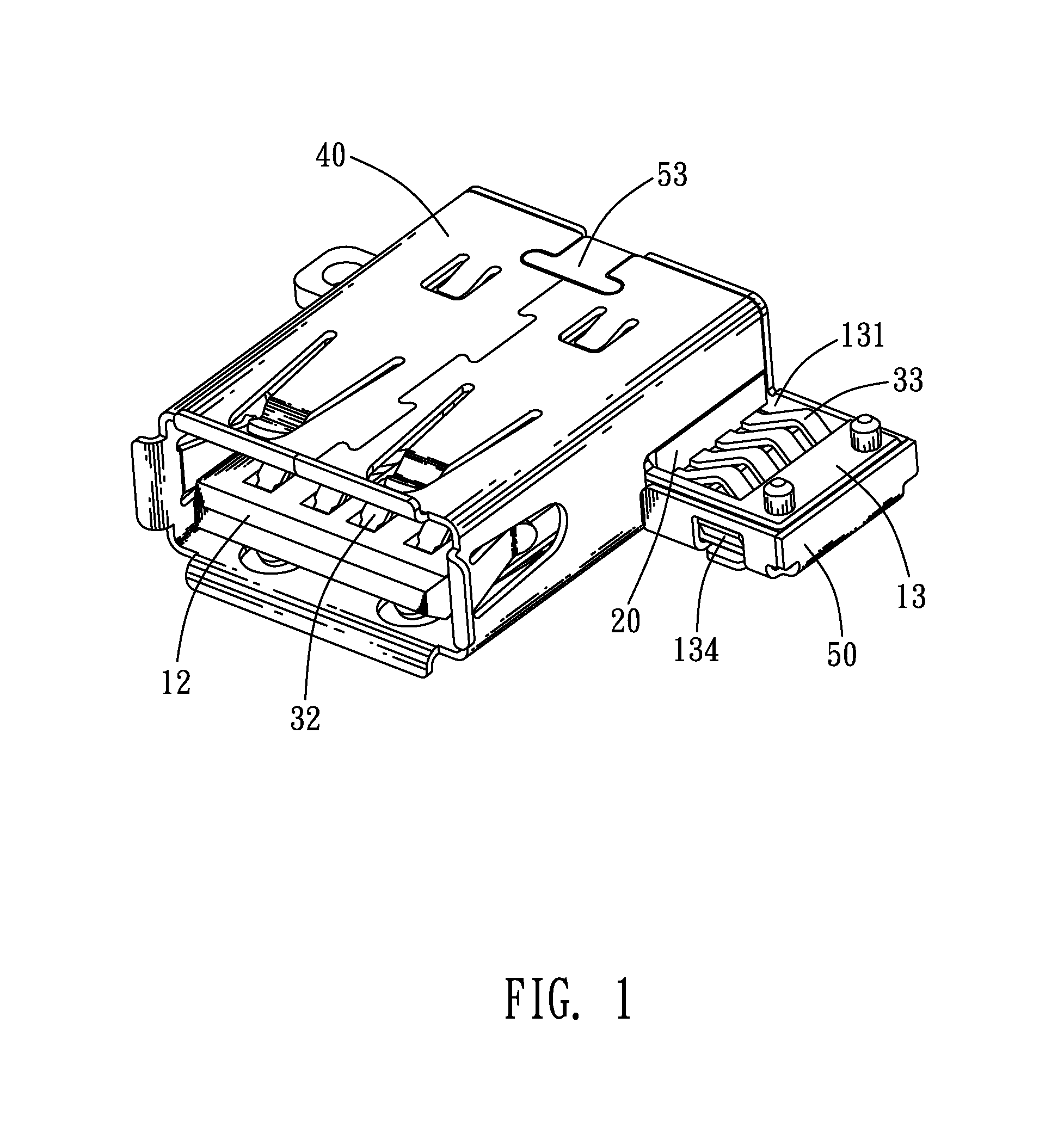
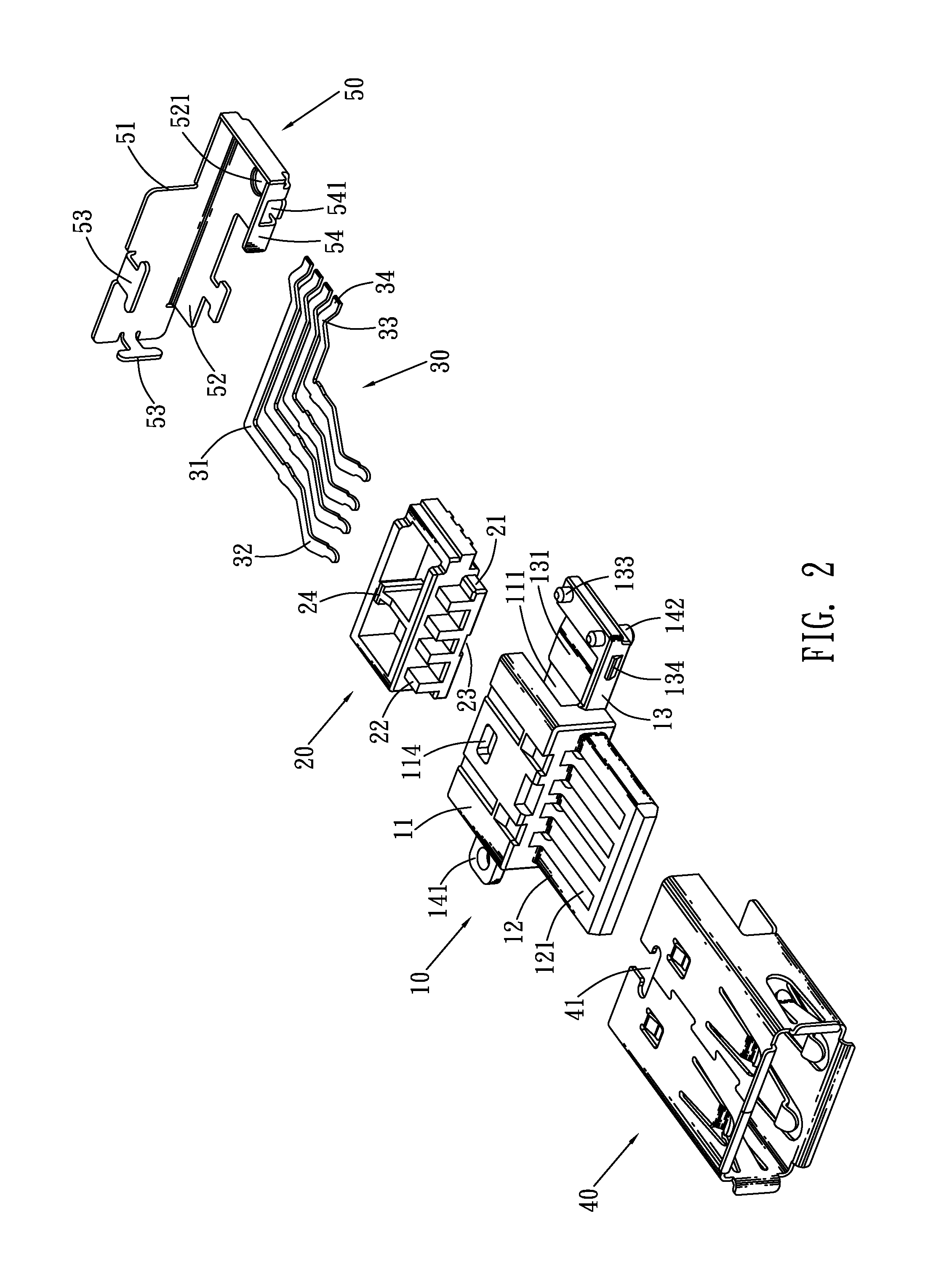
[0013]With reference to FIG. 1 and FIG. 2, an electrical connector in accordance with an embodiment of the present invention includes a main housing 10, an inner housing 20, a plurality of conductive terminals 30 and a shielding shell.
[0014]Referring to FIG. 1, FIG. 2, FIG. 4 and FIG. 5, the main housing 10 has a base body 11, a tongue board 12 extending forward from a front of the base body 11, and a bearing board 13 extending sideward from one side face of the base body 11. A top face of the bearing board 13 defines a receiving cavity 131 penetrating rearward through the bearing board 13. A back of the base body 11 is concaved forward to form a receiving chamber 111 penetrating sideward through the base body 11 to communicate with the receiving cavity 131. The inner housing 20 is disposed in the receiving chamber 111 of the main housing 10.
[0015]The conductive terminals 30 each has a fastening arm 31 placed horizontally. One end of the fastening arm 31 extends forward and is arche...
PUM
 Abstract
Description
Claims
Application Information