Fan assembly for an appliance

a technology for fan assemblies and appliances, applied in the direction of appliances, lighting and heating apparatus, liquid fuel engines, etc., can solve the problems of lint accumulation within the vent or within the dryer appliance, the performance of the dryer appliance can be negatively affected, and the dryer appliance's performance can be reduced

Inactive Publication Date: 2014-06-12
HAIER US APPLIANCE SOLUTIONS INC
View PDF19 Cites 15 Cited by
  • Summary
  • Abstract
  • Description
  • Claims
  • Application Information

AI Technical Summary

Benefits of technology

[0011]In a second exemplary embodiment, a dryer appliance is provided. The dryer appliance includes a cabinet. The cabinet defines a vent. A drum is rotatably mounted within the cabinet. The drum defines a chamber for receipt of articles for drying. A conduit connects the chamber of the drum and the vent of the cabinet. The conduit places the chamber of the drum and the vent of the cabinet in fluid communication. A motor is in mechanical communication with the drum such that the motor selectively rotates the drum. A fan is disposed within the conduit. The fan has an axis of rotation about which the fan is rotatable. The fan is in mechanical communication with the motor. The fan is rotatable about the axis of rotation by the motor in order to urge a flow of air from the chamber of the drum to the vent of the cabinet through the conduit. The fan defines a radial direction, a circumferential direction, and an axial direction. The fan includes a base coupled to the motor. An annular plate is spaced apart from the base along the axial direction. The annular plate has a first surface and a second surface. The first surface of the annular plate is spaced apart from the second surface of the annular plate along the axial direction. A plurality of low pressure blades is mounted on the first surface of the annular plate and extends away from the first surface of the plate along the axial direction. A plurality of high pressure blades is mounted on the second surface of the annular plate and extends between and connects the annular plate and the base.
[0012]In a third exemplary embodiment, a fan assembly for an appliance is provided. The fan assembly defines a radial direction, a circumferential direction, and an axial direction. The fan assembly includes an annular plate. The annular plate has a first surface and a second surface. The first surface of the annular plate is spaced apart from the second surface of the annular plate along the axial direction. A plurality of low pressure blades is mounted on the first surface of the annular plate and extends away from the first surface of the annular plate along the axial direction. A plurality of high pressure blades is mounted on the second surface of the annular plate and extends away from the second surface of the annular plate along the axial direction.

Problems solved by technology

Conversely, dryer appliance performance can be negatively affected if the heating assembly generates a low volume of heated air.
In addition, performance of the dryer appliance can decrease over time.
For example, lint can accumulate within the dryer appliance's vent or within the household ductwork, e.g., because owners rarely clean the vent and / or ductwork.
Such lint can hinder or resist the flow of heated air and thereby negatively affect dryer appliance performance, e.g., leading to increased drying time.
However, adding a second motor to a dryer appliance is expensive.
Thus, adding the second motor can increase the cost of the dryer appliance and negatively affect a consumer's desire to purchase the dryer appliance.

Method used


Image

  • Fan assembly for an appliance
  • Fan assembly for an appliance
  • Fan assembly for an appliance

Examples


Embodiment Construction

[0022]Reference now will be made in detail to embodiments of the invention, one or more examples of which are illustrated in the drawings. Each example is provided by way of explanation of the invention, not limitation of the invention. In fact, it will be apparent to those skilled in the art that various modifications and variations can be made in the present invention without departing from the scope or spirit of the invention. For instance, features illustrated or described as part of one embodiment can be used with another embodiment to yield a still further embodiment. Thus, it is intended that the present invention covers such modifications and variations as come within the scope of the appended claims and their equivalents.

[0023]As used herein, the term “article” may refer to but need not be limited to fabrics, textiles, garments (or clothing), and linens. Furthermore, the term “load” or “laundry load” refers to the combination of articles that may be washed together in a was...


PUM


Abstract

A fan assembly for an appliance is provided. The fan assembly includes a first plurality of blades and a second plurality of blades. Performance of the appliance can be improved and uniform fan assembly performance over a wide range of pressures can be provided by including the first and second pluralities of blades.

Description

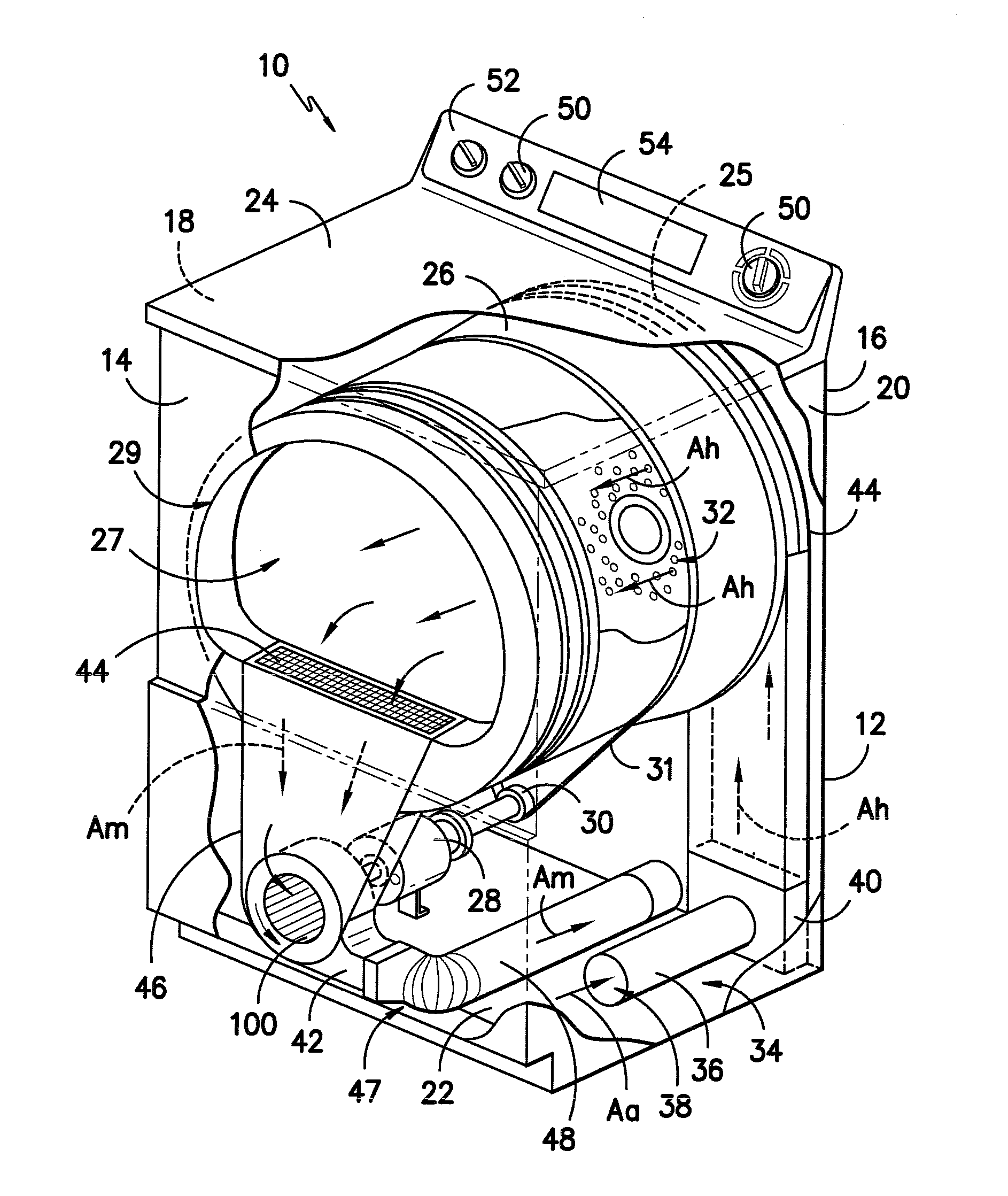
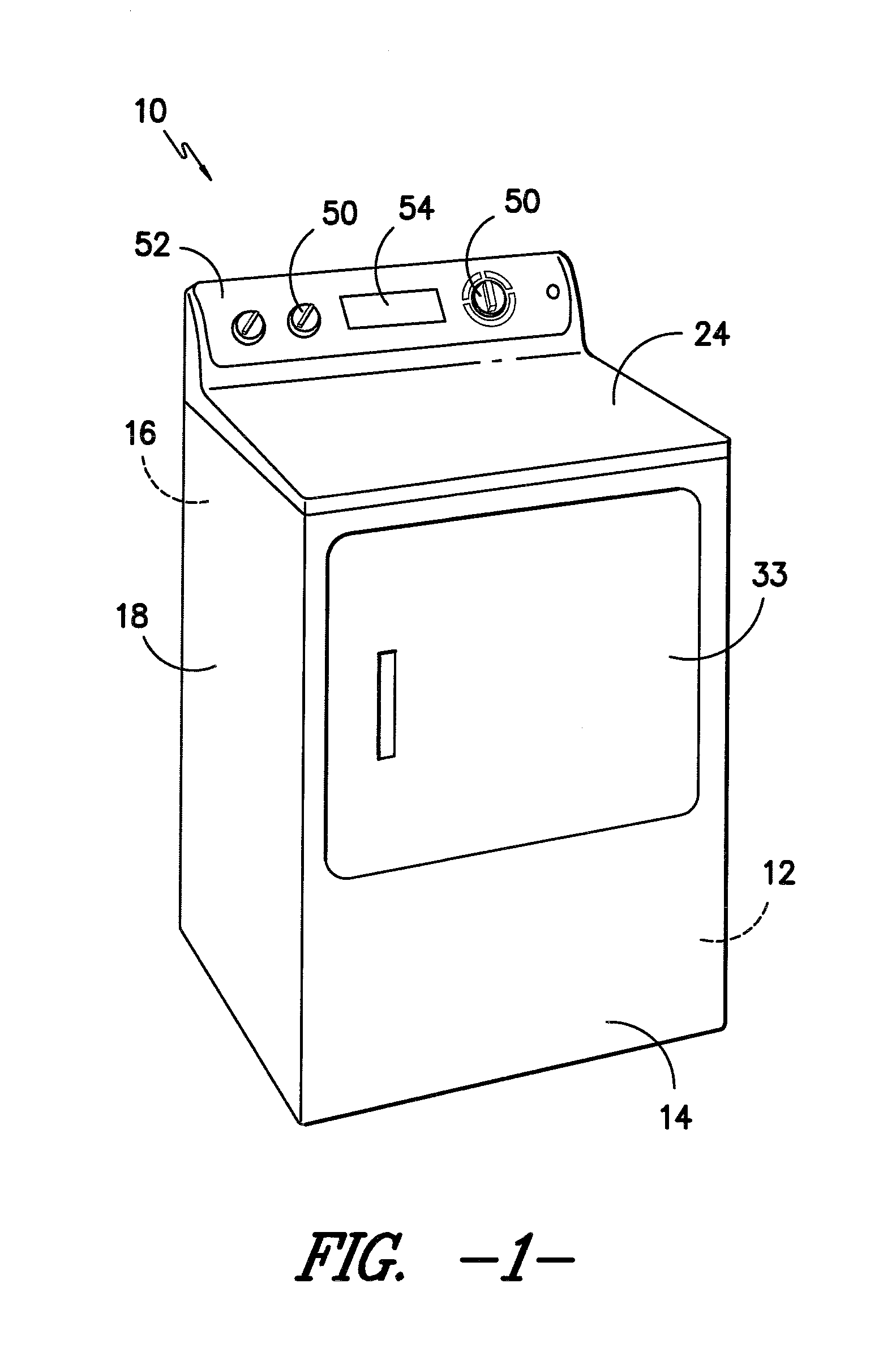
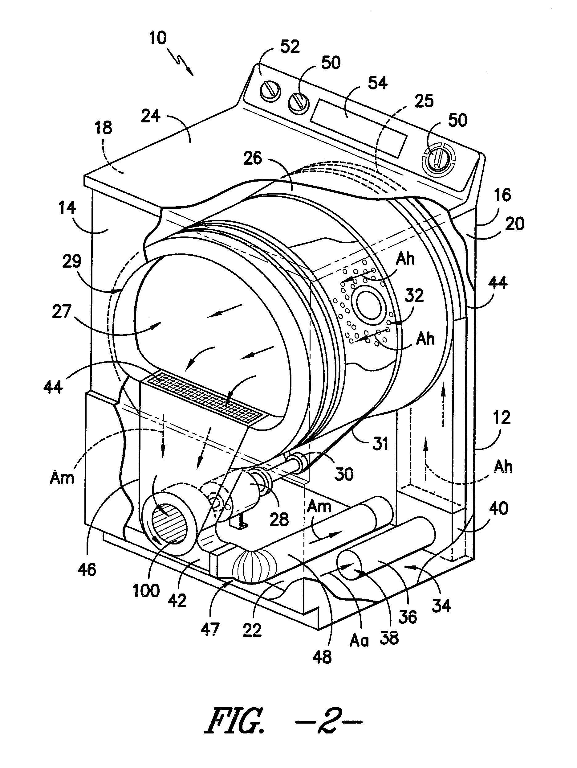
FIELD OF THE INVENTION[0001]The present subject matter relates generally to fan assemblies for appliances, e.g., dryer appliances.BACKGROUND OF THE INVENTION[0002]Dryer appliances generally include a cabinet with a drum rotatably mounted therein. A motor can selectively rotate the drum during operation of the dryer appliance, e.g., to tumble articles located within a chamber defined by the drum. Dryer appliances also generally include a heater assembly that passes heated air through the chamber of the drum in order to dry moisture laden articles disposed within the chamber. To circulate heated air, the heater assembly can include a fan. The fan can be rotated by the motor that also rotates the drum.[0003]During operation of the dryer appliance, the fan of the heater assembly can urge a flow of heated air into the chamber of the drum. Such heated air can absorb moisture from articles disposed within the chamber. In turn, the fan can urge moisture laden air out of the chamber through ...

Claims


Application Information

Patent Timeline
Patent Type & Authority Applications(United States)
IPC IPC(8): F04D3/00F26B11/02
CPCF26B3/04F26B2210/12F04D25/166F04D29/281F04D29/30F04D29/286
Inventor MCLAIN, JOSEPH LEE
Owner HAIER US APPLIANCE SOLUTIONS INC
Why Eureka
Try Eureka